

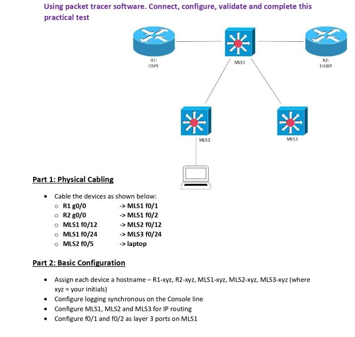
Using packet tracer software. Connect, configure, validate and complete this practical test R1: OSPE R2: MLS1...
Fantastic news! We've Found the answer you've been seeking!
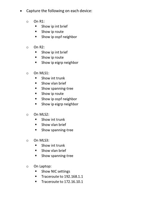
Question:
Expert Answer:

Posted Date:
