

You have to design Mini Computational Unit (MCU) that performs following operations. 1. Transfer: that transfers...
Fantastic news! We've Found the answer you've been seeking!
Question:
Transcribed Image Text:
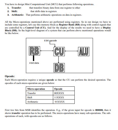
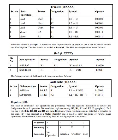
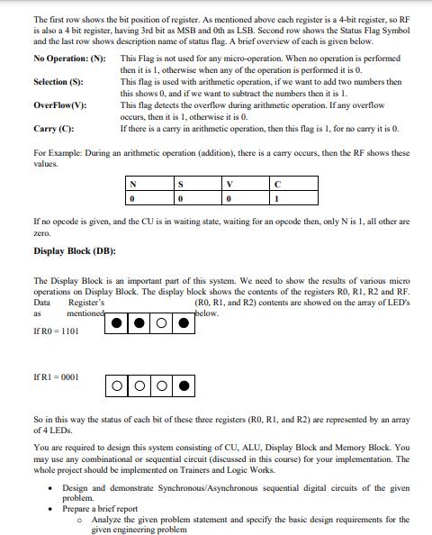
You have to design Mini Computational Unit (MCU) that performs following operations. 1. Transfer: that transfers binary data from one register to other that shifts data in registers 2. Shift: 3. Arithmetic: That performs arithmetic operations on data in registers. All the Micro-operations mentioned above are performed using registers. So in our design we have to include some registers, let's say this memory block as Register Bank (RB) along with control signals that are controlled by a Control Unit (CU). And for the display of the results we need to have a Display Block (DB). So the high-level diagram of a system that can perform above mentioned operations would be like below. RB- 6 bit opcode 4 bit data CU DB Opcode: Each Micro-operation requires a unique opcode so that the CU can perform the desired operation. The opcodes of each micro-operation are given below: Micro-operation Transfer Shift Arithmetic ALU Opcode 00XXXX 11XXXX 01XXXX First bits from MSB identifies the tration. E.g., if the given input for opcode is 000000, then it shows transfer operation has to be performed. The micro-operations have many sub-operations. The sub- operations of each, with opcodes are as follows. Sr. No 11 2 3 4 15 Sr. No 1 2 Sub- operation Load Load Load Move Move Sr. No 1 2 Sub-operation Shift Left Shift Right Source User User User R2 R1 Addition Subtraction When the source is User (U), it means we have to provide data on input, so that it can be loaded into the specified register. The data should be loaded in Parallel. The Shift micro-operations are as follows: Shift (11XXXX) Source R2 R1 Sub-operation Source R0, R2 RI, RO Transfer (00XXXX) Designation Symbol R1 R2 RO RI R2 Bit position 3 Status Flag N The Sub-operations of Arithmetic micro-operation is as follows: Arithmetic (01XXXX) Designation Description R1 R2 Designation Symbol R2 R1 R1-U R2-U RO-U R1+R2 R2-RI No Operation R2 sl R2 R1-st R1 2 S Symbol R1 - R2+RO R2-R0+ R1'+1 Registers (RB): For sake of simplicity, the operations are performed with the registers mentioned as source and designation for each operation. We need four registers namely R0, R1, R2 and RF (Flag register). Each register is of 4 bits. R0, R1 and R2 are Data Registers. These registers contains data that is provided by the user. RF (Flag register) is a Status Register and is used to show the status of various micro operations. The Format of status shown by each bit of Flag register is as follows 1 V 0 Opcode C 000000 000001 000100 000010 000011 Selection Overflow Carry Opcode 110000 110011 Opcode 010000 010011 The first row shows the bit position of register. As mentioned above each register is a 4-bit register, so RF is also a 4 bit register, having 3rd bit as MSB and 0th as LSB. Second row shows the Status Flag Symbol and the last row shows description name of status flag. A brief overview of each is given below. No Operation: (N): Selection (S): OverFlow (V): This Flag is not used for any micro-operation. When no operation is performed then it is 1, otherwise when any of the operation is performed it is 0. This flag is used with arithmetic operation, if we want to add two numbers then this shows 0, and if we want to subtract the numbers then it is 1. Carry (C): For Example: During an arithmetic operation (addition), there is a carry occurs, then the RF shows these values. This flag detects the overflow during arithmetic operation. If any overflow occurs, then it is 1, otherwise it is 0. If there is a carry in arithmetic operation, then this flag is 1, for no carry it is 0. If R0=1101 IfRI=0001 N 0 S 0 V 0 с If no opcode is given, and the CU is in waiting state, waiting for an opcode then, only N is 1, all other are zero. Display Block (DB): 1 The Display Block is an important part of this system. We need to show the results of various micro operations on Display Block. The display block shows the contents of the registers RO, R1, R2 and RF. Data Register's (RO, RI, and R2) contents are showed on the array of LED's below. as mentioned So in this way the status of each bit of these three registers (RO, RI, and R2) are represented by an array of 4 LEDs. You are required to design this system consisting of CU, ALU, Display Block and Memory Block. You may use any combinational or sequential circuit (discussed in this course) for your implementation. The whole project should be implemented on Trainers and Logic Works. Design and demonstrate Synchronous/Asynchronous sequential digital circuits of the given problem. Prepare a brief report o Analyze the given problem statement and specify the basic design requirements for the given engineering problem You have to design Mini Computational Unit (MCU) that performs following operations. 1. Transfer: that transfers binary data from one register to other that shifts data in registers 2. Shift: 3. Arithmetic: That performs arithmetic operations on data in registers. All the Micro-operations mentioned above are performed using registers. So in our design we have to include some registers, let's say this memory block as Register Bank (RB) along with control signals that are controlled by a Control Unit (CU). And for the display of the results we need to have a Display Block (DB). So the high-level diagram of a system that can perform above mentioned operations would be like below. RB- 6 bit opcode 4 bit data CU DB Opcode: Each Micro-operation requires a unique opcode so that the CU can perform the desired operation. The opcodes of each micro-operation are given below: Micro-operation Transfer Shift Arithmetic ALU Opcode 00XXXX 11XXXX 01XXXX First bits from MSB identifies the tration. E.g., if the given input for opcode is 000000, then it shows transfer operation has to be performed. The micro-operations have many sub-operations. The sub- operations of each, with opcodes are as follows. Sr. No 11 2 3 4 15 Sr. No 1 2 Sub- operation Load Load Load Move Move Sr. No 1 2 Sub-operation Shift Left Shift Right Source User User User R2 R1 Addition Subtraction When the source is User (U), it means we have to provide data on input, so that it can be loaded into the specified register. The data should be loaded in Parallel. The Shift micro-operations are as follows: Shift (11XXXX) Source R2 R1 Sub-operation Source R0, R2 RI, RO Transfer (00XXXX) Designation Symbol R1 R2 RO RI R2 Bit position 3 Status Flag N The Sub-operations of Arithmetic micro-operation is as follows: Arithmetic (01XXXX) Designation Description R1 R2 Designation Symbol R2 R1 R1-U R2-U RO-U R1+R2 R2-RI No Operation R2 sl R2 R1-st R1 2 S Symbol R1 - R2+RO R2-R0+ R1'+1 Registers (RB): For sake of simplicity, the operations are performed with the registers mentioned as source and designation for each operation. We need four registers namely R0, R1, R2 and RF (Flag register). Each register is of 4 bits. R0, R1 and R2 are Data Registers. These registers contains data that is provided by the user. RF (Flag register) is a Status Register and is used to show the status of various micro operations. The Format of status shown by each bit of Flag register is as follows 1 V 0 Opcode C 000000 000001 000100 000010 000011 Selection Overflow Carry Opcode 110000 110011 Opcode 010000 010011 The first row shows the bit position of register. As mentioned above each register is a 4-bit register, so RF is also a 4 bit register, having 3rd bit as MSB and 0th as LSB. Second row shows the Status Flag Symbol and the last row shows description name of status flag. A brief overview of each is given below. No Operation: (N): Selection (S): OverFlow (V): This Flag is not used for any micro-operation. When no operation is performed then it is 1, otherwise when any of the operation is performed it is 0. This flag is used with arithmetic operation, if we want to add two numbers then this shows 0, and if we want to subtract the numbers then it is 1. Carry (C): For Example: During an arithmetic operation (addition), there is a carry occurs, then the RF shows these values. This flag detects the overflow during arithmetic operation. If any overflow occurs, then it is 1, otherwise it is 0. If there is a carry in arithmetic operation, then this flag is 1, for no carry it is 0. If R0=1101 IfRI=0001 N 0 S 0 V 0 с If no opcode is given, and the CU is in waiting state, waiting for an opcode then, only N is 1, all other are zero. Display Block (DB): 1 The Display Block is an important part of this system. We need to show the results of various micro operations on Display Block. The display block shows the contents of the registers RO, R1, R2 and RF. Data Register's (RO, RI, and R2) contents are showed on the array of LED's below. as mentioned So in this way the status of each bit of these three registers (RO, RI, and R2) are represented by an array of 4 LEDs. You are required to design this system consisting of CU, ALU, Display Block and Memory Block. You may use any combinational or sequential circuit (discussed in this course) for your implementation. The whole project should be implemented on Trainers and Logic Works. Design and demonstrate Synchronous/Asynchronous sequential digital circuits of the given problem. Prepare a brief report o Analyze the given problem statement and specify the basic design requirements for the given engineering problem
Expert Answer:
Answer rating: 100% (QA)
To design the Mini Computational Unit MCU as described well need to create a schematic using Logic W... View the full answer

Related Book For 
College Algebra With Modeling And Visualization
ISBN: 9780134418049
6th Edition
Authors: Gary Rockswold
Posted Date:
Students also viewed these accounting questions
-
Planning is one of the most important management functions in any business. A front office managers first step in planning should involve determine the departments goals. Planning also includes...
-
ABC Pty Ltd would like to set up a Virtualisation Platform on their organisation. You have been hired by Company to be their network and system administrator to implement virtualisation for...
-
Log in to ca.finance.yahoo.com and find the profile for Magna International (MGA). Construct the debt ratio, debt/(debt + equity), for the firm. Now calculate Magna's debt ratio by using the market...
-
The American Trends Panel (ATP), created by Pew Research Center, is a nationally representative panel of randomly selected U.S. adults. Wave 64 survey of the panel was conducted from March 19, 2020...
-
Consider the following cash flow profile and assume MARR is 10 percent/year and the finance rate is 4 percent/ year. a. Determine the MIRR for this project. b. Is this project economically...
-
Hill Company uses budgets in controlling costs. The August 2014 budget report for the company's Assembling Department is as follows. The monthly budget amounts in the report were based on an expected...
-
explain diagram of ER model and relational model and attach their diagrams too Each cinema is identified by its name and has its residency at an address which consists of a street and city only....
-
b. Prepare all consolidating entries needed to prepare consolidated statements for 20X5. (If no entry is required for a transaction/event, select "No journal entry required" in the first account...
-
On 1 July 2019 Wills, a bricklayer, sold a one-tonne truck to his brother-in-law, Burke, a cartage contractor, for $20,400. Wills had previously attempted to sell the truck to dealers but the best...
-
A suction-cup-tipped arrow is secured vertically to the outer edge of a turntable designed for playing LP phonograph records (ask your parents). A motion detector is situated 60 cm away. The...
-
The model structure shown in Figure Q1 comprises two iden- tical rigid links each of length L with a pin joint connecting them. The bottom end of the structure has a rotational spring of stiffness K...
-
At steady state, air enters at 22.7 C and 100 kPa. For noise control, the velocity of the entering air cannot exceed 1.58 m/s. For temperature control, the temperature of the air at the exit cannot...
-
Water-Jetpack that you'll design needs to lift a 100kg person. It will have two jets (as seen in the picture) with 5cm nozzle diameter each. a. Is a frame of reference put on earth an inertial one or...
-
(ii) As part of a corrosion test, nickel (II) immersed in boiling 10% phosphoric acid exhibited a corrosion rate of 154 mils/year. Given nickel's mass density of 8.90g/cm and atomic weight of 58.7...
-
VIN = 2V. Determine Vo1 (in Volts) ? O a. 2.7 Vie of O b. -2.7 an OC-13.0 O d-13 fer the: V..r=0:7 V dide D %3D O e. 1.3
-
The population of Detroit, Michigan, decreased from 1,027,974 in 1990 to 688,701 in 2013 (Source: U.S. Census Bureau). Find the average rate of change in the population of Detroit, Michigan, over the...
-
Use synthetic division to divide the first polynomial by the second. x43x5x + 2x - 16 x-3
-
Find the volume and surface area of the sphere satisfying the given condition, where r is the radius and d is the diameter. Approximate values to the nearest tenth. r = 4.1 inches
-
If possible, find AB and BA. -3 5 27 B= 07
-
A surface with \(N_{0}\) adsorption centers has \(N\left(\leq N_{0}ight)\) gas molecules adsorbed on it. Show that the chemical potential of the adsorbed molecules is given by \[ \mu=k T \ln...
-
Assuming that the latent heat of vaporization of water \(L_{\mathrm{V}}=2260 \mathrm{~kJ} / \mathrm{kg}\) is independent of temperature and the specific volume of the liquid phase is negligible...
-
Define a quantity \(J\) as \[ J=E-N \mu=T S-P V \] Show that for a system in the grand canonical ensemble \[ \overline{(\Delta J)^{2}}=k T^{2} C_{V}+\left\{\left(\frac{\partial U}{\partial...

Study smarter with the SolutionInn App