

The drawing shown is of a mounting fixture to locate and orient a rod (not shown) through
Question:
The drawing shown is of a mounting fixture to locate and orient a rod (not shown) through the large bore. The fixture will be bolted to a frame through the four bolt holes that are countersunk to recess the bolt heads. The bolt holes have too much clearance to properly align the rod, so the fixture will be aligned with two locating pins in the frame that will fit in the ∅6 hole and slot.
(a) Determine the minimum diameter allowed for the countersink.
(b) Determine the maximum depth allowed for the countersink.
(c) Determine the diameter of the bolt holes at MMC.
(d) Identify every feature that qualifies as a feature of size.
(e) The width of the base is specified with a basic dimension of 60, with no tolerance. What are the minimum and maximum allowed dimensions for the base width? Explain how they are determined.
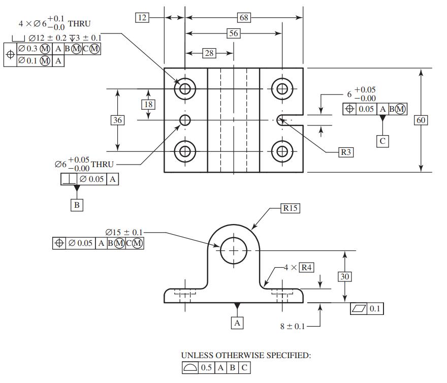
(f) Describe the datum features A, B, and C. Describe their corresponding datums. Describe the datum reference frame that is defined by applying A, B, and C in that order. Describe how the part is stabilized by these datums. Explain why this is more appropriate for this application than using the edges of the base for datums B and C.
(g) If datum feature B is produced with a diameter of ∅6.00, what is the diameter of the tolerance zone in which its axis must lie? What if it is produced at ∅6.05?
(h) If the bolt holes are produced at ∅6.0, what is the diameter of the tolerance zones locating the bolt hole pattern with respect to the true position specified by the basic dimensions? What if the bolt holes are produced at ∅6.1?
(i) If the bolt holes are produced at ∅6.0, what is the diameter of the tolerance zones locating the position of the bolt holes with respect to one another? What if the bolt holes are produced at ∅6.1?
(j) Explain why the M modifier is appropriate for the bolt hole position tolerance.
(k) For the large bore, explain what provides control of each of the following: orientation, straightness of its center axis, and cylindricity of its surface.
(l) Assume the part is cast, and the casting operation can provide a surface profile tolerance of less than 0.5. Which surfaces can likely be left in the as-cast condition without compromising any of the requirements of the drawing? How would this change if the drawing were modified to use the edges of the base as datum features B and C, while still maintaining the functional goals for the alignment of the rod?
Step by Step Answer:
a The countersink diameter is specified as 12 02 The minimum countersink diameter is 118 b The countersink depth is specified ...View the full answer


Shigley's Mechanical Engineering Design
ISBN: 9780073398204
10th Edition
Authors: Richard Budynas, Keith Nisbett
