

(a) Design the circuit shown in Figure P7.18 such that (I_{D Q}=0.8 mathrm{~mA}), (V_{D S Q}=3.2 mathrm{~V},...
Question:
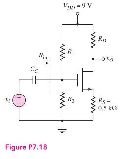
(a) Design the circuit shown in Figure P7.18 such that \(I_{D Q}=0.8 \mathrm{~mA}\), \(V_{D S Q}=3.2 \mathrm{~V}, R_{\text {in }}=160 \mathrm{k} \Omega\), and \(f_{L}=16 \mathrm{~Hz}\). The transistor parameters are \(K_{n}=0.5 \mathrm{~mA} / \mathrm{V}^{2}, V_{T N}=1.2 \mathrm{~V}\), and \(\lambda=0\).
(b) What is the midband voltage gain?
(c) Determine the magnitude of the voltage gain at (i) \(f=5 \mathrm{~Hz}\), (ii) \(f=14 \mathrm{~Hz}\), and (iii) \(f=25 \mathrm{~Hz}\).
(d) Sketch the Bode plot of the voltage gain magnitude and phase.
Step by Step Answer:

This question has not been answered yet.
You can Ask your question!
Related Book For 

Microelectronics Circuit Analysis And Design
ISBN: 9780071289474
4th Edition
Authors: Donald A. Neamen
Question Posted:
