

(a) The circuit shown in Figure P5.40 is to be designed such that (I_{C Q}=) (0.5 mathrm{~mA})...
Question:
(a) The circuit shown in Figure P5.40 is to be designed such that \(I_{C Q}=\) \(0.5 \mathrm{~mA}\) and \(V_{C E Q}=2.5 \mathrm{~V}\). Assume \(\beta=120\). Sketch the load line and plot the \(Q\)-point.
(b) Pick standard values of resistors that are close to the designed values. Assume that the standard resistor values vary by \(\pm 10\) percent. Plot the load lines and \(Q\)-point values for the maximum and minimum values of \(R_{B}\) and \(R_{C}\) values (four \(Q\)-point values).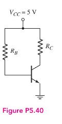
Step by Step Answer:

This question has not been answered yet.
You can Ask your question!
Related Book For 

Microelectronics Circuit Analysis And Design
ISBN: 9780071289474
4th Edition
Authors: Donald A. Neamen
Question Posted:
