

Consider the bipolar op-amp configuration in Figure 11.49. The bias voltages are (pm 10 mathrm{~V}), as shown,
Question:
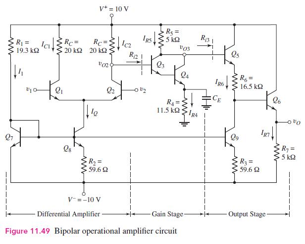
Consider the bipolar op-amp configuration in Figure 11.49. The bias voltages are \(\pm 10 \mathrm{~V}\), as shown, the current \(I_{R 7}\) is to be \(I_{R 7}=3 \mathrm{~mA}\), and the maximum dc power dissipation in the circuit is to be \(120 \mathrm{~mW}\). The output voltage is to be \(v_{o}=0\) for \(v_{1}=v_{2}=0\). Design the circuit, using reasonable resistance and current values. What is the overall differential-mode voltage gain?
Fantastic news! We've Found the answer you've been seeking!
Step by Step Answer:

Answered By
Sufiyan Ahmed Tariq
I am a Chartered Accountant and an Associate Public & Finance Accountant. I also hold a bachelors of Commerce degree. I have over 8 years of experience in accounting, finance and auditing. Through out my career, I have worked with many leading multinational organisation.
I have helped a number of students in studies by teaching them key concepts of subjects like accounting, finance, corporate law and auditing. I help students understanding the complex situation by providing them daily life examples.
I can help you in the following subject / areas:
a) Accounting;
b) Finance;
c) Commerce;
d) Auditing; and
e) Corporate Law.
7+ Reviews
17+ Question Solved
Related Book For 

Microelectronics Circuit Analysis And Design
ISBN: 9780071289474
4th Edition
Authors: Donald A. Neamen
Question Posted:
