

Consider the circuit in Figure P15.16. (a) Derive the expressions for the magnitude and phase of the
Question:
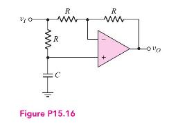
Consider the circuit in Figure P15.16.
(a) Derive the expressions for the magnitude and phase of the voltage transfer function.
(b) Plot the phase versus frequency for \(R=10 \mathrm{k} \Omega\) and \(C=15.9 \mathrm{nF}\). [Note: this filter is referred to as an all-pass filter in that the magnitude of the voltage gain is constant, but the phase of the output voltage changes with frequency.]
Step by Step Answer:

This question has not been answered yet.
You can Ask your question!
Related Book For 

Microelectronics Circuit Analysis And Design
ISBN: 9780071289474
4th Edition
Authors: Donald A. Neamen
Question Posted:
