

Consider the circuit shown in Figure P11.39. The circuit and transistor parameters are (V^{+}=+3 mathrm{~V}, V^{-}=-3 mathrm{~V},
Question:
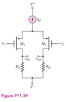
Consider the circuit shown in Figure P11.39. The circuit and transistor parameters are \(V^{+}=+3 \mathrm{~V}, V^{-}=-3 \mathrm{~V}, R_{D}=360 \mathrm{k} \Omega, I_{Q}=12 \mu \mathrm{A}\), \(V_{T P}=-0.4 \mathrm{~V}, K_{p}=30 \mu \mathrm{A} / \mathrm{V}^{2}\), and \(\lambda=0\). The output resistance of the current source is \(R_{o}=4 \mathrm{M} \Omega\).
(a) Determine the \(Q\)-points of the transistors for \(v_{1}=v_{2}=0\).
(b) Determine the differential- and common-mode voltage gains for (i) \(v_{O}=v_{D 1}-v_{D 2}\) and (ii) \(v_{O}=v_{D 2}\).
Fantastic news! We've Found the answer you've been seeking!
Step by Step Answer:

Answered By
Rahul Sorout
I'm Rahul Sorout. I graduated from high school with an 80% overall and a 99% in Mathematics. I am in my last year of graduation with Math. Also, I am working as a tutor of Mathematics and subject matter expert of Calculus on online platforms. I am very interested and have extensive knowledge in Mathematics ( Calculus, Algebra, Trigonometry, Statistics and probability etc.). I speak English and Hindi.
0 Reviews
10+ Question Solved
Related Book For 

Microelectronics Circuit Analysis And Design
ISBN: 9780071289474
4th Edition
Authors: Donald A. Neamen
Question Posted:
