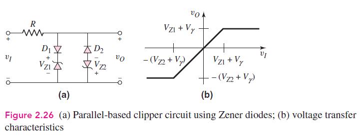
Consider the parallel clipper circuit in Figure 2.26 in the text. Assume (V_{Z 1}=6 mathrm{~V}, V_{Z 2}=4
Question:
Consider the parallel clipper circuit in Figure 2.26 in the text. Assume \(V_{Z 1}=6 \mathrm{~V}, V_{Z 2}=4 \mathrm{~V}\), and \(V_{\gamma}=0.7 \mathrm{~V}\) for all diodes. For \(v_{I}=10 \sin \omega t\), sketch \(v_{O}\) versus time over two periods of the input signal.

Step by Step Answer:
Related Book For 

Microelectronics Circuit Analysis And Design
ISBN: 9780071289474
4th Edition
Authors: Donald A. Neamen
Question Posted:


