

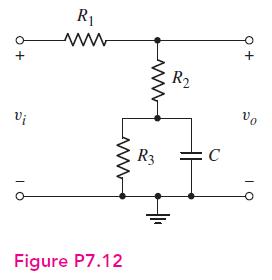
For the circuit shown in Figure P7.12, the parameters are (R_{1}=10 mathrm{k} Omega), (R_{2}=10 mathrm{k} Omega, R_{3}=40
Question:
For the circuit shown in Figure P7.12, the parameters are \(R_{1}=10 \mathrm{k} \Omega\), \(R_{2}=10 \mathrm{k} \Omega, R_{3}=40 \mathrm{k} \Omega\), and \(C=10 \mu \mathrm{F}\).
(a) What is the value of the voltage transfer function \(V_{o} / V_{i}\) at very low frequencies?
(b) Determine the value of the voltage transfer function at very high frequencies.
(c) Derive the expression for the voltage transfer function \(T(s)=V_{o}(s) / V_{i}(s)\). Put the expression in the form \(T(s)=K\left(1+s \tau_{A}\right) /\left(1+s \tau_{B}\right)\). What are the values of \(K, \tau_{A}\), and \(\tau_{B}\) ?
Fantastic news! We've Found the answer you've been seeking!
Step by Step Answer:

Answered By
Lisper Wanja
I am an experienced and highly motivated writer with a passion for the skills listed. I have a proven track record of my expertise and my aim is to deliver quality, well-detailed and plagiarism free projects. My genuine passion for writing combined with my ongoing professional development through school and research makes me an ideal candidate within for any assignment.
233+ Reviews
388+ Question Solved
Related Book For 

Microelectronics Circuit Analysis And Design
ISBN: 9780071289474
4th Edition
Authors: Donald A. Neamen
Question Posted:
