

For the differential amplifier in Figure P11.31 the parameters are (R_{1}=50 mathrm{k} Omega) and (R_{D}=24 mathrm{k} Omega).
Question:
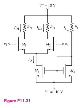
For the differential amplifier in Figure P11.31 the parameters are \(R_{1}=50 \mathrm{k} \Omega\) and \(R_{D}=24 \mathrm{k} \Omega\). The transistor parameters are: \(K_{n}=0.25 \mathrm{~mA} / \mathrm{V}^{2}, \lambda=0\), and \(V_{T N}=2 \mathrm{~V}\).
(a) Determine \(I_{1}, I_{Q}, I_{D 1}, V_{D S 1}\), and \(V_{D S 4}\) when \(v_{1}=v_{2}=0\).
(b) Draw the dc load line and plot the \(Q\)-point for transistor \(M_{2}\).
(c) What are the maximum and minimum values of the common-mode input voltage?
Step by Step Answer:

This question has not been answered yet.
You can Ask your question!
Related Book For 

Microelectronics Circuit Analysis And Design
ISBN: 9780071289474
4th Edition
Authors: Donald A. Neamen
Question Posted:
