

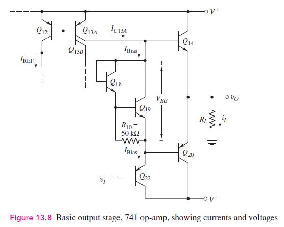
The basic bias circuit of the output transistors of the 741 op-amp is shown in Figure P13.23.
Question:
The basic bias circuit of the output transistors of the 741 op-amp is shown in Figure P13.23.
(a) Sketch the small-signal equivalent circuit.
(b) Assuming \(V_{A}=50 \mathrm{~V}\) and using the parameters described in Example 13.3, determine the equivalent small-signal resistance \(R_{e q}=v_{x} / i_{x}\).
Data From Example 13.3:-
Fantastic news! We've Found the answer you've been seeking!
Step by Step Answer:

Answered By
Susan Juma
I'm available and reachable 24/7. I have high experience in helping students with their assignments, proposals, and dissertations. Most importantly, I'm a professional accountant and I can handle all kinds of accounting and finance problems.
15+ Reviews
45+ Question Solved
Related Book For 

Microelectronics Circuit Analysis And Design
ISBN: 9780071289474
4th Edition
Authors: Donald A. Neamen
Question Posted:
