

The circuit in Figure P11.91 has two bipolar differential amplifiers in cascade, biased with ideal current sources
Question:
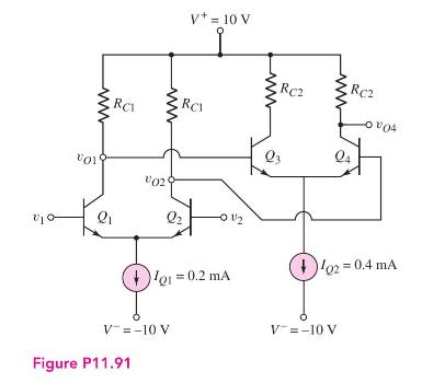
The circuit in Figure P11.91 has two bipolar differential amplifiers in cascade, biased with ideal current sources \(I_{Q 1}\) and \(I_{Q 2}\). Assume the transistor parameters are \(\beta=180\) and \(V_{A}=\infty\).
(a) Design the circuit such that \(v_{o 1}=v_{o 2}=2 \mathrm{~V}\) and \(v_{O 4}=6 \mathrm{~V}\) when \(v_{1}=v_{2}=0\).
(b) Determine the differential-mode voltage gains \(A_{d 1}=\left(v_{o 1}-v_{o 2}\right) / v_{d}\) and \(A_{d}=v_{o 4} / v_{d}\).
Fantastic news! We've Found the answer you've been seeking!
Step by Step Answer:

Answered By
Tamil Elakkiya Rajendran
I'm currently involved in the research in the field of Biothermodynamics, Metabolic pathway analysis and computational Biology. I always prefer to share my knowledge whatever I have learnt through my degree whenever time permits.
2+ Reviews
10+ Question Solved
Related Book For 

Microelectronics Circuit Analysis And Design
ISBN: 9780071289474
4th Edition
Authors: Donald A. Neamen
Question Posted:
