

The circuit in Figure P15.18 is a bandpass filter. (a) Derive the expression for the voltage transfer
Question:
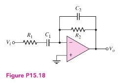
The circuit in Figure P15.18 is a bandpass filter.
(a) Derive the expression for the voltage transfer function \(T(s)\).
(b) If \(R_{1}=10 \mathrm{k} \Omega\), determine \(R_{2}, C_{1}\), and \(C_{2}\) such that the magnitude of the midband gain is 50 and the cutoff frequencies are \(200 \mathrm{~Hz}\) and \(5 \mathrm{kHz}\).
Fantastic news! We've Found the answer you've been seeking!
Step by Step Answer:

Answered By
Chiranjib Thakur
I have no tutoring experience yet, but I can share my skills and knowledge gained from my education and work experiences. I have been a CPA since 2012 with 6 years of work experience in internal auditing and 4 years of work experience in accounting at the supervisory level.
1+ Reviews
10+ Question Solved
Related Book For 

Microelectronics Circuit Analysis And Design
ISBN: 9780071289474
4th Edition
Authors: Donald A. Neamen
Question Posted:
