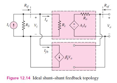
The circuit parameters of the ideal shunt-shunt amplifier shown in Figure 12.14 are (A_{z f}=0.20 mathrm{~V} /
Question:
The circuit parameters of the ideal shunt-shunt amplifier shown in Figure 12.14 are \(A_{z f}=0.20 \mathrm{~V} / \mu \mathrm{A}, \beta_{g}=4.25 / \mu \mathrm{A} / \mathrm{V}\), and \(R_{i}=R_{o}=500 \Omega\). Determine the values and units of \(A_{z}, R_{i f}\), and \(R_{o f}\).

Fantastic news! We've Found the answer you've been seeking!
Step by Step Answer:
Related Book For 

Microelectronics Circuit Analysis And Design
ISBN: 9780071289474
4th Edition
Authors: Donald A. Neamen
Question Posted:


