

The circuit shown in Figure P5.30 is to be designed such that (I_{C Q}=0.8 mathrm{~mA}) and (V_{C
Question:
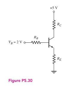
The circuit shown in Figure P5.30 is to be designed such that \(I_{C Q}=0.8 \mathrm{~mA}\) and \(V_{C E Q}=2 \mathrm{~V}\) for the case when (a) \(R_{E}=0\) and (b) \(R_{E}=1 \mathrm{k} \Omega\). Assume \(\beta=80\). (c) The transistor in Figure P5.30 is replaced with one with a value of \(\beta=120\). Using the results of parts (a) and (b), determine the \(Q\)-point values \(I_{C Q}\) and \(V_{C E Q}\). Which design shows the smallest change in \(Q\)-point values?
Fantastic news! We've Found the answer you've been seeking!
Step by Step Answer:

Answered By
SUMAN DINDA
I LIKE TO TEACH STUDENTS. SO, I START MYSELF AS A PRIVATE TUTOR. I TEACH STUDENTS OF DIFFERENT CLASSES. I HAVE ALSO DONE BACHELOR OF EDUCATION DEGREE(B.ED). DURING THIS COURSE I HAD TO TEACH IN A SCHOOL. SO I HAVE A GOOD EXPERIENCE IN TEACHING.
1+ Reviews
10+ Question Solved
Related Book For 

Microelectronics Circuit Analysis And Design
ISBN: 9780071289474
4th Edition
Authors: Donald A. Neamen
Question Posted:
