

Two feedback configurations are shown in Figures P12.15 (a) and (b). At low input voltages, the two
Question:
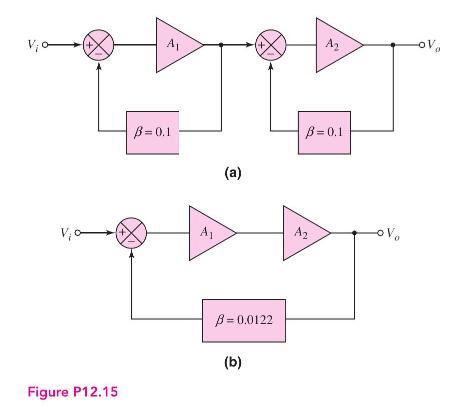
Two feedback configurations are shown in Figures P12.15 (a) and (b). At low input voltages, the two gains are \(A_{1}=A_{2}=90\) and at higher input voltages, the gains change to \(A_{1}=A_{2}=60\). Determine the change in closed-loop gain, \(A_{f}=V_{o} / V_{i}\), for the two feedback circuits. (See Figure 12.4.) Which feedback configuration will result in less distortion in the output signal?
Fantastic news! We've Found the answer you've been seeking!
Step by Step Answer:

Answered By
User l_1230876
I have over 12 years in academic writing and I believe this gives me enough experience in the field. I specialize in Business subjects and Humanities. I have the ability to write excellent papers and I deliver timely and quality papers. I understand what plagiarism is and I will do enswathing to ensure my papers are original. I am ready to work and deliver correct and accurate solutions to students if given the opportunity. Thank you.
0 Reviews
10+ Question Solved
Related Book For 

Microelectronics Circuit Analysis And Design
ISBN: 9780071289474
4th Edition
Authors: Donald A. Neamen
Question Posted:
