

Building upon Problem 11.11, assume a (60 mathrm{~Hz}) nominal system frequency, that the bus fault actually occurs
Question:
Building upon Problem 11.11, assume a \(60 \mathrm{~Hz}\) nominal system frequency, that the bus fault actually occurs on the line between buses five and two but at the bus two end, and that the fault is cleared by opening breakers B21 and B52. Again, neglecting the loads, assume that the generator at bus three is modeled with the classical generator model having a per unit value (on its 800 MVA base) of \(\mathrm{X}_{d}^{\prime}=0.24\), and \(\mathrm{H}=3\) p.u.-s. Before the fault occurs the generator is delivering \(300 \mathrm{MW}\) into the infinite bus at unity power factor (hence its terminal voltage is not 1.05 as was assumed in Example 6.9). Further, assume the fault is cleared after 3 cycles.
Determine:
(a) the initial generator one power angle,
(b) the power angle when the fault is cleared, and
(c) the maximum value of the power angle using the equal area criteria.
Problem 11.11
Repeat Problem 11.10, except assume there is a three-phase-to-ground bolted short circuit at bus five.
Problem 11.10
For the five bus system from Example 6.9, assume the transmission lines and transformers are modeled with just their per unit reactance (e.g., neglect their resistance and B shunt values). If bus one is assumed to be an infinite bus, what is the equivalent (Thévenin) reactance looking into the system from the bus three terminal? Neglect any impedances associated with the loads.
Example 6.9
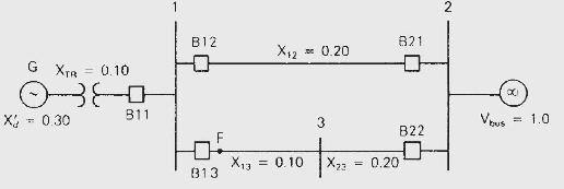
The synchronous generator in Figure 11.4 is initially operating in the steady-state condition given in Example 11.3 when a permanent three-phase-to-ground bolted short circuit occurs on line 1-3 at bus 3 . The fault is cleared by opening the circuit breakers at the ends of line \(1-3\) and line \(2-3\). These circuit breakers then remain open. Calculate the critical clearing angle. As in previous examples, \(\mathrm{H}=\) 3.0 p.u.-s, \(p_{m}=1.0\) per unit and \(\omega_{\text {p.u. }}=1.0\) in the swing equation.
Figure 11.4
Step by Step Answer:


Power System Analysis And Design
ISBN: 9781305632134
6th Edition
Authors: J. Duncan Glover, Thomas Overbye, Mulukutla S. Sarma
