

Consider a simple circuit configuration shown in Figure 9.24 to calculate the fault currents (I_{1}, I_{2}), and
Question:
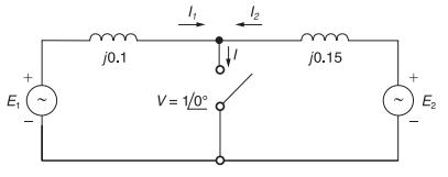
Consider a simple circuit configuration shown in Figure 9.24 to calculate the fault currents \(I_{1}, I_{2}\), and \(I\) with the switch closed.
(a) Compute \(E_{1}\) and \(E_{2}\) prior to the fault based on the prefault voltage \(V=1 \angle 0^{\circ}\) and then, with the switch closed, determine \(I_{1}, I_{2}\), and \(I\).
(b) Start by ignoring prefault currents, with \(E_{1}=E_{2}=1 \angle 0^{\circ}\). Then superimpose the load currents, which are the prefault currents, \(I_{1}=-I_{2}=1 \angle 0^{\circ}\). Compare the results with those of part (a).
Figure 9.24
Fantastic news! We've Found the answer you've been seeking!
Step by Step Answer:

Answered By
Antony Sang
I am a research and academic writer whose work is outstanding. I always have my customer's interests at heart. Time is an important factor in our day to day life so I am always time conscious. Plagiarism has never been my thing whatsoever. I give best Research Papers, Computer science and IT papers, Lab reports, Law, programming, Term papers, English and literature, History, Math, Accounting, Business Studies, Finance, Economics, Business Management, Chemistry, Biology, Physics, Anthropology, Sociology, Psychology, Nutrition, Creative Writing, Health Care, Nursing, and Articles.
2+ Reviews
10+ Question Solved
Related Book For 

Power System Analysis And Design
ISBN: 9781305632134
6th Edition
Authors: J. Duncan Glover, Thomas Overbye, Mulukutla S. Sarma
Question Posted:
