

Consider a single-phase electric system shown in Figure 3.33. Transformers are rated as follows: X-Y 15 MVA,
Question:
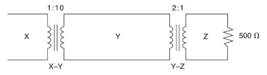
Consider a single-phase electric system shown in Figure 3.33. Transformers are rated as follows:
X-Y 15 MVA, 13.8/138 kV, leakage reactance 10\%
Y-Z 15 MVA, 138/69 kV, leakage reactance 8\%
With the base in circuit Y chosen as \(15 \mathrm{MVA}, 138 \mathrm{kV}\), determine the perunit impedance of the \(500 \Omega\) resistive load in circuit \(Z\), referred to circuits Z, Y, and X. Neglecting magnetizing currents, transformer resistances, and line impedances, draw the impedance diagram in per unit.
Step by Step Answer:

This question has not been answered yet.
You can Ask your question!
Related Book For 

Power System Analysis And Design
ISBN: 9781305632134
6th Edition
Authors: J. Duncan Glover, Thomas Overbye, Mulukutla S. Sarma
Question Posted:
