

Figure P7-65 is a simplified diagram of a sample-hold circuit. When the switch is in position (mathrm{A}),
Question:
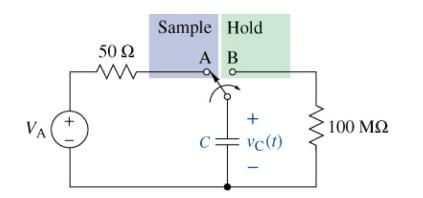
Figure P7-65 is a simplified diagram of a sample-hold circuit. When the switch is in position \(\mathrm{A}\), the circuit is in the sample mode and the capacitor voltage must charge to at least \(99 \%\) of the source voltage \(V_{\mathrm{A}}\) in less than \(1 \mu \mathrm{s}\). When the switch is moved to position \(\mathrm{B}\), the circuit is in the hold mode and the capacitor must retain at least \(99 \%\) of \(V\) A for at least \(1 \mathrm{~ms}\). Select a capacitor that meets these constraints.
Fantastic news! We've Found the answer you've been seeking!
Step by Step Answer:
In the sample mode we have the following requirement 099VAVA 1e sTc 0991eusT...View the full answer

Answered By
Amit Kumar
I am a student at IIT Kanpur , which is one of the prestigious colleges in INDIA.
Cleared JEE Advance in 2017.I am a flexible teacher because I understand that all students learn in different ways and at different paces. When teaching, I make sure that every student has a grasp of the subject before moving on.
I will help student to get the basic understanding clear. I believe friendly behavior with student can help both the student and the teacher.
I love science and my students do the same.
44+ Reviews
166+ Question Solved
Related Book For 

The Analysis And Design Of Linear Circuits
ISBN: 9781119913023
10th Edition
Authors: Roland E. Thomas, Albert J. Rosa, Gregory J. Toussaint
Question Posted:
