

Find the transfer function (T_{mathrm{V}}(s)=V_{2}(s) / V_{1}(s) ) for the circuit in Figure P12-45 . (a) Use
Question:
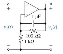
Find the transfer function \(T_{\mathrm{V}}(s)=V_{2}(s) / V_{1}(s\) ) for the circuit in Figure P12-45 .
(a) Use MATLAB to generate a Bode plot of your transfer function. From the Bode plots, estimate the amplitude and phase of the steady-state output for each of the following input signals
\[
\begin{gathered}
v_{1}(t)=10 \cos 10 t \mathrm{~V}, \\
v_{1}(t)=10 \cos 100 t \mathrm{~V}, \text { and } \\
v_{1}(t)=10 \cos 1000 t \mathrm{~V} .
\end{gathered}
\]
(b) calculate the actual output amplitude and phase for these three inputs and compare the results with your estimates.
Fantastic news! We've Found the answer you've been seeking!
Step by Step Answer:
a b The following MATLAB code creates t...View the full answer

Answered By
Raunak Agarwal
Teaching is my hobby and now my profession. I teach students of CA and CFA(USA) in batches of 100 students and have a 5 year experience.
1+ Reviews
10+ Question Solved
Related Book For 

The Analysis And Design Of Linear Circuits
ISBN: 9781119913023
10th Edition
Authors: Roland E. Thomas, Albert J. Rosa, Gregory J. Toussaint
Question Posted:
