

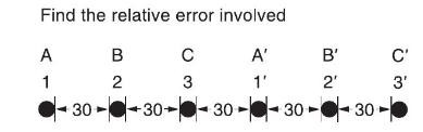
For the case of double-circuit, bundle-conductor lines, the same method indicated in Problem 4.27 applies with (r^{prime})
Question:
For the case of double-circuit, bundle-conductor lines, the same method indicated in Problem 4.27 applies with \(r^{\prime}\) replaced by the bundle's GMR in the calculation of the overall GMR.
Now consider a double-circuit configuration shown in Figure 4.36 that belongs to a \(500-\mathrm{kV}\), three-phase line with bundle conductors of three subconductors at \(21 \mathrm{in}\). spacing. The GMR of each subconductor is given to be \(0.0485 \mathrm{ft}\).
Determine the inductive reactance of the line in ohms per mile per phase. You may use
\(\mathrm{X}_{\mathrm{L}}=0.2794 \log \frac{\mathrm{GMD}}{\mathrm{GMR}} \Omega / \mathrm{mi} /\) phase
Problem 4.27
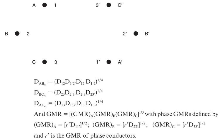
Figure 4.34 shows double-circuit conductors' relative positions in segment 1 of transposition of a completely transposed three-phase overhead transmission line. The inductance is given by
\(\mathrm{L}=2 \times 10^{-7} \ln \frac{\mathrm{GMD}}{\mathrm{GMR}} \mathrm{H} / \mathrm{m} /\) phase Where GMD \(=\left(\mathrm{D}_{\mathrm{AB}_{\mathrm{eq}}} \mathrm{D}_{\mathrm{BC}_{\mathrm{eq}}} \mathrm{D}_{\mathrm{AC}_{\mathrm{eq}}}ight)^{1 / 3}\)
With mean distances defined by equivalent spacings
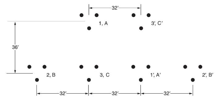
Now consider a 345-kV, three-phase, double-circuit line with phase conductor’s GMR of 0.0588 ft and the horizontal conductor configuration shown in Figure 4.35.
Step by Step Answer:


Power System Analysis And Design
ISBN: 9781305632134
6th Edition
Authors: J. Duncan Glover, Thomas Overbye, Mulukutla S. Sarma
