

For the circuit given in Problem 13.3, replace the circuit elements by their discrete-time equivalent circuits and
Question:
For the circuit given in Problem 13.3, replace the circuit elements by their discrete-time equivalent circuits and write nodal equations in a form suitable for computer solution of the sending-end and receiving-end voltages. Give equations for all dependent sources. Assume \(\mathrm{E}=1000 \mathrm{~V}, \mathrm{~L}_{\mathrm{R}}=\) \(20 \mathrm{mH}, Z_{c}=100 \Omega, v=2 \times 10^{8} \mathrm{~m} / \mathrm{s}, l=40 \mathrm{~km}\), and \(\Delta t=0.02 \mathrm{~ms}\).
Problem 13.3
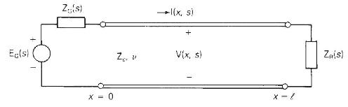
Referring to the single-phase two-wire lossless line shown in Figure 13.3, the receiving end is terminated by an inductor with \(2 \mathrm{~L}_{\mathrm{R}}\) henries. The source voltage at the sending end is a step, \(e_{\mathrm{G}}(t)=\mathrm{E} u_{-1}(t)\) with \(\mathrm{Z}_{\mathrm{G}}=Z_{c}\). Both the line and inductor are initially unenergized. Determine and plot the voltage at the center of the line \(v(l / 2, t)\) versus time \(t\).
Figure 13.3
Step by Step Answer:

This question has not been answered yet.
You can Ask your question!


Power System Analysis And Design
ISBN: 9781305632134
6th Edition
Authors: J. Duncan Glover, Thomas Overbye, Mulukutla S. Sarma
