

From (4.6.22) and (4.10.4), the series inductance and shunt capacitance of a three-phase overhead line are [
Question:
From (4.6.22) and (4.10.4), the series inductance and shunt capacitance of a three-phase overhead line are
\[
\begin{aligned}
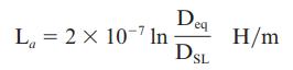
\mathrm{L}_{a} & =2 \times 10^{-7} \ln \left(\mathrm{D}_{\mathrm{eq}} / \mathrm{D}_{\mathrm{SL}}ight)=\frac{\mu_{0}}{2 \pi} \ln \left(\mathrm{D}_{\mathrm{eq}} / \mathrm{D}_{\mathrm{SL}}ight) \quad \mathrm{H} / \mathrm{m} \\
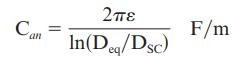
\mathrm{C}_{a n} & =\frac{2 \pi \varepsilon_{0}}{\ln \left(\mathrm{D}_{\mathrm{eq}} / \mathrm{D}_{\mathrm{SC}}ight)} \mathrm{F} / \mathrm{m} \\
\text { where } \mu_{0} & =4 \pi \times 10^{-7} \mathrm{H} / \mathrm{m} \text { and } \varepsilon_{0}=\left(\frac{1}{36 \pi}ight) \times 10^{-9} \mathrm{~F} / \mathrm{m} .
\end{aligned}
\]
Using these equations, determine formulas for surge impedance and velocity of propagation of an overhead lossless line. Then determine the surge impedance and velocity of propagation for the three-phase line given in Example 4.5. Assume positive-sequence operation. Neglect line losses as well as the effects of the overhead neutral wires and the earth plane.
Eq. (4.6.22)
Eq. (4.10.4)
Example 4.5
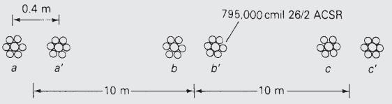
Each of the 1,590,000 cmil conductors in Example 4.4 is replaced by two 795,000 cmil ACSR 26/2 conductors, as shown in Figure 4.15. Bundle spacing is 0.40 m. Flat horizontal spacing is retained, with 10 m between adjacent bundle centers. Calculate the inductive reactance of the line and compare it with that of Example 4.4.
Step by Step Answer:


Power System Analysis And Design
ISBN: 9781305632134
6th Edition
Authors: J. Duncan Glover, Thomas Overbye, Mulukutla S. Sarma
