

In Figure P16-53, the source at bus 1 supplies two load buses through transmission lines with wire
Question:
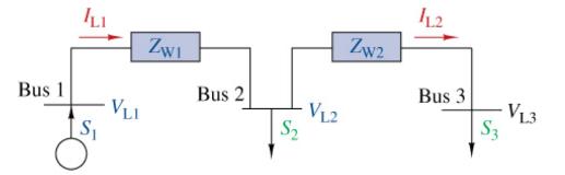
In Figure P16-53, the source at bus 1 supplies two load buses through transmission lines with wire impedances of \(Z_{\mathrm{W}_{1}}=6+j 33 \Omega /\) phase and \(Z_{\mathrm{W}_{2}}=3+j 15 \Omega /\) phase. The load at bus 2 draws an apparent power 4 MVA at a lagging power factor of 095. The load at bus 3 draws an apparent power of 3 MVA at a lagging power factor of 0.9. The line voltage at bus 3 is \(V_{\mathrm{L} 3}=\) \(138 \mathrm{kV}(\mathrm{rms})\). Find the apparent power produced by the source at bus 1 , the source power factor, and the line voltages at bus 1 and bus 2.
Fantastic news! We've Found the answer you've been seeking!
Step by Step Answer:
Find the complex power at bus 3 S3 S31 pf 1pf 3 09JV1092 27j13077 MVA Find the c...View the full answer

Answered By
BUCHUPALLI PAVANKUMAR REDDY
As a Civil Engineering tutor, I am a highly skilled and knowledgeable professional with a passion for teaching and sharing my expertise with others. I have a degree in Civil Engineering, as well as extensive experience working in the field, which has provided me with a deep understanding of the subject matter.
My teaching style is highly engaging and interactive, and I have a talent for breaking down complex concepts into simple, easy-to-understand terms. I am patient and supportive with my students, and I work hard to create a positive learning environment where everyone feels comfortable asking questions and exploring new ideas.
In addition to my technical knowledge and teaching skills, I also possess excellent communication skills and a strong work ethic. I am highly organized and detail-oriented, and I take pride in ensuring that my students receive the highest quality instruction and support.
Above all, I am deeply committed to helping my students succeed, and I take great satisfaction in seeing them achieve their academic and professional goals. My dedication, expertise, and passion for teaching make me an invaluable resource for anyone seeking to learn more about Civil Engineering.
0 Reviews
10+ Question Solved
Related Book For 

The Analysis And Design Of Linear Circuits
ISBN: 9781119913023
10th Edition
Authors: Roland E. Thomas, Albert J. Rosa, Gregory J. Toussaint
Question Posted:
