

Line impedances for the power system shown in Figure 10.47 are (Z_{12}=Z_{23}=3.0+j 40.0 Omega), and (Z_{24}=6.0+j 80.0
Question:
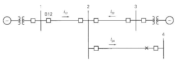
Line impedances for the power system shown in Figure 10.47 are \(Z_{12}=Z_{23}=3.0+j 40.0 \Omega\), and \(Z_{24}=6.0+j 80.0 \Omega\). Reach for the zone 3 B12 impedance relays is set for \(100 \%\) of line \(1-2\) plus \(120 \%\) of line \(2-4\)
(a) For a bolted three-phase fault at bus 4, show that the apparent primary impedance "seen" by the B12 relays is \(Z_{\text {apparent }}=Z_{12}+Z_{24}+\left(\mathrm{I}_{32} / \mathrm{I}_{12}ight) Z_{24}\)
where \(\left(I_{32} / I_{12}ight)\) is the line \(2-3\) to line 1-2 fault current ratio.
(b) If \(\left|I_{32}ight| I_{12} \mid>\) 0.20 , does the B12 relay see the fault at bus 4 ?
This problem illustrates the "infeed effect." Fault currents from line 2-3 can cause the zone 3 B12 relay to underreach. As such, remote backup of line 2-4 at B12 is ineffective.
Step by Step Answer:


Power System Analysis And Design
ISBN: 9781305632134
6th Edition
Authors: J. Duncan Glover, Thomas Overbye, Mulukutla S. Sarma
