

One way to liquefy a gas is to flash it through a valve. However, this requires that
Question:
One way to liquefy a gas is to flash it through a valve. However, this requires that the inlet conditions to the valve be at a state where an expansion will cause the gas to flash into a saturated mixture of liquid and vapor. Consider a situation where helium gas is at 10 bar and the desired pressure of the liquid is 1 bar. In order to produce liquid helium, the inlet state to the throttling process must lie between the two states identified as a and b on the P-h diagram shown in Figure P6.15A. For an inlet pressure of 10 bar, this temperature range is 2.53 K ≤ T ≤ 7.60 K for helium.
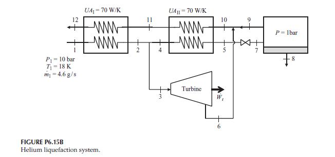
One possible way to achieve this low temperature at the entrance to the valve is shown in Figure P6.15B. This system is known as a liquefaction system.
In this system, the helium gas is supplied at 10 bar, 18 K at a flow rate of 4.6 g/s.
This gas is cooled further using two heat exchangers. The cooling of the gas is accomplished by mixing the cold saturated vapor leaving the separator and the cold gas at the exhaust of a small turbine operating between the high and low pressures of the system. The UA product of each heat exchanger is 70 W/K. The separator operates at a pressure of 1 bar. Manufacturer’s performance data for the turbine relate the turbine temperatures and mass flow rate with two empirical equations,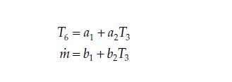 In these turbine performance equations a1 = 4.6 K, a2 = 0.1, b1 = 3.75 g/s, and b2 = −0.125 g/s-K. Write and solve a simulation for this helium liquefaction system and determine the,
a. Unknown temperatures in the cycle (K)
b. Heat transfer rate in each heat exchanger (W)
c. Liquid helium mass flow rate leaving the separator (g/s)
d. Power delivered by the turbine (W)
Evaluate the system to determine how the inlet helium flow rate at State 2 influences the liquid helium production rate and the turbine output power. Plot the following parameters as a function of the inlet helium mass flow rate for the range 3.4 ≤ m 1 ≤ 5.0 g/s,
e. Liquid helium mass flow rate leaving the separator (g/s)
f. Quality of the helium leaving the valve at State 7
g. Turbine output power (W)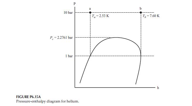
Step by Step Answer:

This question has not been answered yet.
You can Ask your question!

Thermal Energy Systems Design And Analysis
ISBN: 9781138735897
2nd Edition
Authors: Steven G. Penoncello
