

Open PowerWorld Simulator case Problem 6_49. This case is identical to Example 6.9, except that the transformer
Question:
Open PowerWorld Simulator case Problem 6_49. This case is identical to Example 6.9, except that the transformer between buses 1 and 5 is now a tap-changing transformer with a tap range between 0.9 and 1.1 and a tap step size of 0.006 25 . The tap is on the high side of the transformer. As the tap is varied between 0.975 and 1.1, show the variation in the reactive power output of generator \(1, \mathrm{~V}_{5}, \mathrm{~V}_{2}\), and the total real power losses.
Example 6.9
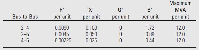
Figure 6.2 shows a single-line diagram of a five-bus power system. Input data are given in Tables 6.1, 6.2, and 6.3. As shown in Table 6.1, bus 1, to which a generator is connected, is the swing bus. Bus 3, to which a generator and a load are connected, is a voltage-controlled bus. Buses 2, 4, and 5 are load buses. Note that the loads at buses 2 and 3 are inductive since \(\mathrm{Q}_{2}=-\mathrm{Q}_{\mathrm{L} 2}=-2.8\) and \(-\mathrm{Q}_{\mathrm{L} 3}=\) -0.4 are negative.
For each bus \(k\), determine which of the variables \(\mathrm{V}_{k}, \delta_{k}, \mathrm{P}_{k}\), and \(\mathrm{Q}_{k}\) are input data and which are unknowns. Also, compute the elements of the second row of \(\boldsymbol{Y}_{\text {bus }}\).
Figure 6.2
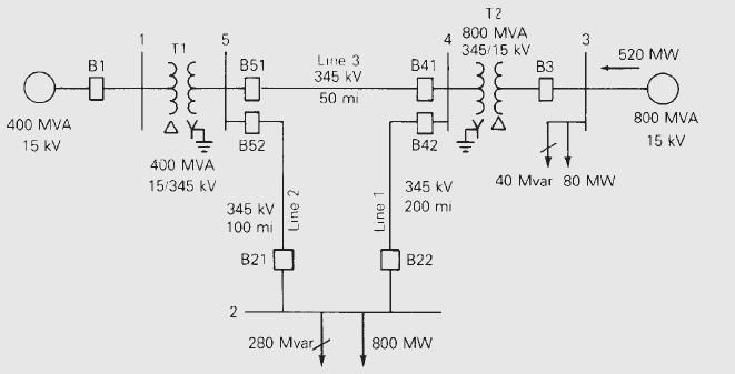
Table 6.1
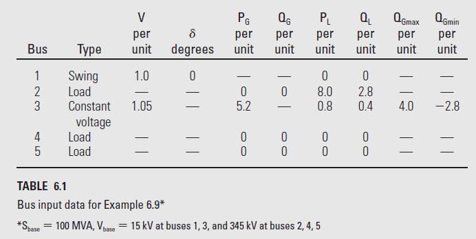
Table 6.2
Step by Step Answer:


Power System Analysis And Design
ISBN: 9781305632134
6th Edition
Authors: J. Duncan Glover, Thomas Overbye, Mulukutla S. Sarma
