

Redo Example 6.17 with the assumption that the per-unit reactance on the line between buses 2 and
Question:
Redo Example 6.17 with the assumption that the per-unit reactance on the line between buses 2 and 5 is changed from 0.05 to 0.03.
Example 6.17
Determine the dc power flow solution for the five bus system from Example 6.9.
Example 6.9
Figure 6.2 shows a single-line diagram of a five-bus power system. Input data are given in Tables 6.1, 6.2, and 6.3. As shown in Table 6.1, bus 1, to which a generator is connected, is the swing bus. Bus 3, to which a generator and a load are connected, is a voltage-controlled bus. Buses 2, 4, and 5 are load buses. Note that the loads at buses 2 and 3 are inductive since \(\mathrm{Q}_{2}=-\mathrm{Q}_{\mathrm{L} 2}=-2.8\) and \(-\mathrm{Q}_{\mathrm{L} 3}=\) -0.4 are negative.
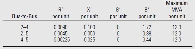
For each bus \(k\), determine which of the variables \(\mathrm{V}_{k}, \delta_{k}, \mathrm{P}_{k}\), and \(\mathrm{Q}_{k}\) are input data and which are unknowns. Also, compute the elements of the second row of \(\boldsymbol{Y}_{\text {bus }}\).
Figure 6.2
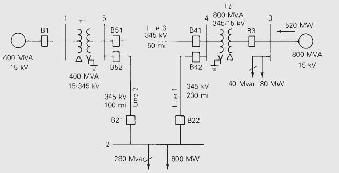
Table 6.1
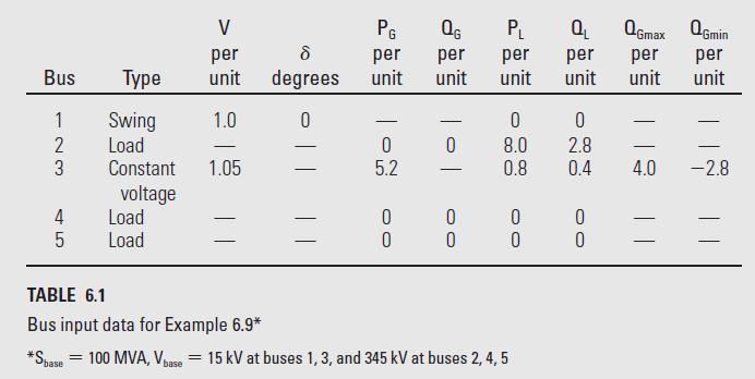
Table 6.2
Step by Step Answer:


Power System Analysis And Design
ISBN: 9781305632134
6th Edition
Authors: J. Duncan Glover, Thomas Overbye, Mulukutla S. Sarma
