

Rework Example 14.3 with R Load = 40 / R Load = 40 / phase,
Question:
Rework Example 14.3 with phase, phase, and phase.
Example 14.3
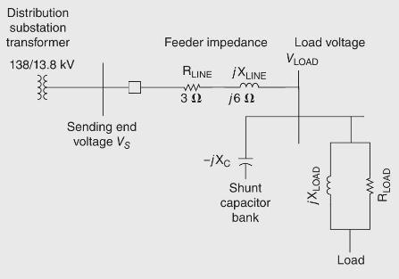
Figure 14.21 shows a single-line diagram of a primary feeder supplying power to a load at the end of the feeder. A shunt capacitor bank is located at the load bus. Assume that the voltage at the sending end of the feeder is above rated and that the load is Y-connected with phase in parallel with load /phase.
(a) With the shunt capacitor bank out of service, calculate the following: (1) line current; (2) voltage drop across the line; (3) load voltage; (4) real and reactive power delivered to the load; (5) load power factor; (6) real and reactive line losses; and (7) real power, reactive power, and apparent power delivered by the distribution substation.
(b) The capacitor bank is Y-connected with a reactance phase. With the shunt capacitor bank in service, redo the calculations. Also calculate the reactive power supplied by the capacitor bank.
(c) Compare the results of (a) and (b).
Step by Step Answer:


Power System Analysis And Design
ISBN: 9781305632134
6th Edition
Authors: J. Duncan Glover, Thomas Overbye, Mulukutla S. Sarma
