

The Automatic Voltage Regulator (AVR) system of a generator is represented by the simplified block diagram shown
Question:
The Automatic Voltage Regulator (AVR) system of a generator is represented by the simplified block diagram shown in Figure 12.15, in which the sensor is modeled by a simple first-order transfer function. The voltage is sensed through a voltage transformer and then rectified through a bridge rectifier. Parameters of the AVR system are given as follows.
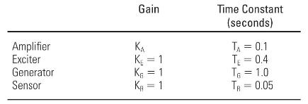

(a) Determine the open-loop transfer function of the block diagram and the closed-loop transfer function relating the generator terminal voltage \(V_{t}(s)\) to the reference voltage \(V_{\text {ref }}(s)\).
(b) For the range of \(K_{A}\) from 0 to 12.16, comment on the stability of the system.
(c) For \(\mathrm{K}_{\mathrm{A}}=10\), evaluate the steady-state step response and steady-state error.
Step by Step Answer:


Power System Analysis And Design
ISBN: 9781305632134
6th Edition
Authors: J. Duncan Glover, Thomas Overbye, Mulukutla S. Sarma
