

The circuit in Figure P12-30 produces a bandstop response for a suitable choice of element values. (a)
Question:
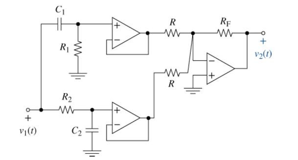
The circuit in Figure P12-30 produces a bandstop response for a suitable choice of element values.
(a) Find the circuit's transfer function.
(b) Identify the elements that control the two cutoff frequencies. Select the element values so that the cutoff frequencies are \(50 \mathrm{krad} / \mathrm{s}\) and \(500 \mathrm{krad} / \mathrm{s}\). Use practical element values with resistances greater than \(10 \mathrm{k} \Omega\) and capacitances less than \(1 \mu \mathrm{F}\). Design your passband gain to be \(+60 \mathrm{~dB}\). After looking at the simulations, can the design specifications be met?
(c) Use MATLAB to plot the Bode magnitude plot for the values you selected.
(d) Simulate your circuit using Multisim and compare the results to the MATLAB output.
Step by Step Answer:
a b c d The circuit consists of a highpass filter connected to a buffer a ...View the full answer


The Analysis And Design Of Linear Circuits
ISBN: 9781119913023
10th Edition
Authors: Roland E. Thomas, Albert J. Rosa, Gregory J. Toussaint
