

The circuit in Figure P7-4 8 is in the zero state when the step function input is
Question:
The circuit in Figure P7-4 8 is in the zero state when the step function input is applied.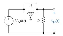
(a) If \(V_{\mathrm{A}}=15 \mathrm{~V}, R=1.5 \mathrm{k} \Omega, L=250 \mathrm{mH}\), and \(C=025 \mu \mathrm{F}\), derive an expression for the voltage \(v_{\mathrm{O}}(t)\) for \(t \geq 0\).
(b) Validate your solution by plotting it using MATLAB and comparing it to a Multisim simulation of the same circuit.
Fantastic news! We've Found the answer you've been seeking!
Step by Step Answer:
a b Perform a source transformation with the voltage s...View the full answer

Answered By
Bree Normandin
Success in writing necessitates a commitment to grammatical excellence, a profound knack to pursue information, and a staunch adherence to deadlines, and the requirements of the individual publication. My background comprises writing research projects, research meta-analyses, literature reviews, white paper reports, multimedia projects, reports for peer-reviewed journals, among others. I work efficiently, with ease and deliver high-quality outputs within the stipulated deadline. I am proficient in APA, MLA, and Harvard referencing styles. I have good taste in writing and reading. I understand that this is a long standing and coupled with excellent research skills, analysis, well-articulated expressions, teamwork, availability all summed up by patience and passion. I put primacy on client satisfaction to gain loyalty, and trust for future projects. As a detail-oriented researcher with extensive experience surpassing eight years crafting high-quality custom written essays and numerous academic publications, I am confident that I could considerably exceed your expectations for the role of a freelance academic writer.
7+ Reviews
21+ Question Solved
Related Book For 

The Analysis And Design Of Linear Circuits
ISBN: 9781119913023
10th Edition
Authors: Roland E. Thomas, Albert J. Rosa, Gregory J. Toussaint
Question Posted:
