

The three-terminal circuit in Figure P14=54. (a) has a bandpass transfer function of the form Show that
Question:
The three-terminal circuit in Figure P14=54. (a) has a bandpass transfer function of the form
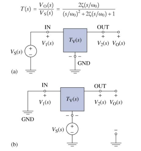
Show that the circuit in Figure P14=54 (b) has a bandstop transfer function of the form
\[
T(s)=\frac{V_{\mathrm{O}}(s)}{V_{\mathrm{S}}(s)}=\frac{\left(s / \omega_{0}ight)^{2}+1}{\left(s / \omega_{0}ight)^{2}+2 \zeta\left(s / \omega_{0}ight)+1}
\]
That is, show that interchanging the input and ground terminals changes a unity-gain bandpass circuit into a unity-gain bandstop circuit.
Fantastic news! We've Found the answer you've been seeking!
Step by Step Answer:
The original input to the circuit is Vs Vss 0 and the original output is Vs Vos 0 With the interchan...View the full answer

Answered By
OTIENO OBADO
I have a vast experience in teaching, mentoring and tutoring. I handle student concerns diligently and my academic background is undeniably aesthetic
3+ Reviews
10+ Question Solved
Related Book For 

The Analysis And Design Of Linear Circuits
ISBN: 9781119913023
10th Edition
Authors: Roland E. Thomas, Albert J. Rosa, Gregory J. Toussaint
Question Posted:
