

Using the bus impedance matrices determined in Problem 9.42. Problem 9.42 (a) Compute the (3 times 3)
Question:
Using the bus impedance matrices determined in Problem 9.42.
Problem 9.42
(a) Compute the \(3 \times 3\) per-unit zero-, positive-, and negative-sequence bus impedance matrices for the power system given in Problem 9.1. Use a base of \(1000 \mathrm{MVA}\) and \(765 \mathrm{kV}\) in the zone of line 1-2.
(b) Using the bus impedance matrices.
Problem 9.1
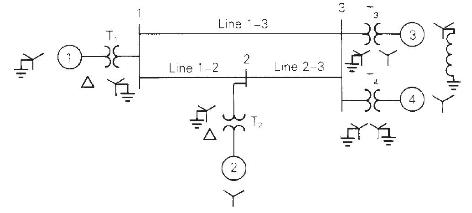
The single-line diagram of a three-phase power system is shown in Figure 9.17. Equipment ratings are given as follows:
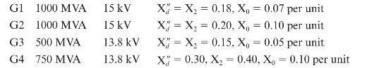
Synchronous generators:
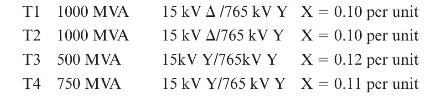
Transformers:
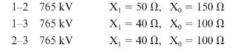
Transmission lines:
The inductor connected to Generator 3 neutral has a reactance of 0.05 per unit using generator 3 ratings as a base. Draw the zero-, positive-, and negative-sequence reactance diagrams using a \(1000-\mathrm{MVA}, 765-\mathrm{kV}\) base in the zone of line 1-2. Neglect the \(\Delta-Y\) transformer phase shifts.
Step by Step Answer:

This question has not been answered yet.
You can Ask your question!


Power System Analysis And Design
ISBN: 9781305632134
6th Edition
Authors: J. Duncan Glover, Thomas Overbye, Mulukutla S. Sarma
