

For the depletion load inverter shown in Figure 16.7(a), assume parameters of (V_{D D}=3.3 mathrm{~V}, V_{T N
Question:
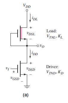
For the depletion load inverter shown in Figure 16.7(a), assume parameters of \(V_{D D}=3.3 \mathrm{~V}, V_{T N D}=0.5 \mathrm{~V}, V_{T N L}=-0.8 \mathrm{~V}, K_{D}=500 \mu \mathrm{A} / \mathrm{V}^{2}\), and \(K_{L}=100 \mu \mathrm{A} / \mathrm{V}^{2}\).
(a) Find the transition points of the driver and load transistors.
(b) Determine \(v_{O}\) for \(v_{I}=3.3 \mathrm{~V}\).
(c) Determine the maximum current and maximum power dissipation in the circuit.
Figure 16.7(a):-
Fantastic news! We've Found the answer you've been seeking!
Step by Step Answer:

Answered By
Asd fgh
sadasmdna,smdna,smdna,msdn,masdn,masnd,masnd,m asd.as,dmas,dma.,sd as.dmas.,dma.,s ma.,sdm.,as mda.,smd.,asmd.,asmd.,asmd.,asm
1+ Reviews
15+ Question Solved
Related Book For 

Microelectronics Circuit Analysis And Design
ISBN: 9780071289474
4th Edition
Authors: Donald A. Neamen
Question Posted:
