

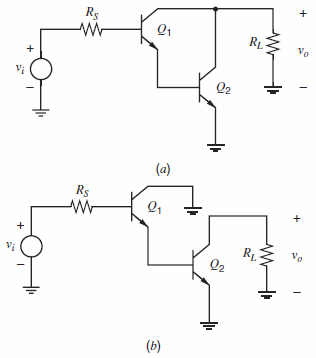
A Darlington stage and a common-collectorcommon-emitter cascade are shown schematically in Fig. 7.40, where R S =
Question:
(a) Calculate the low-frequency small-signal voltage gain Ï…o/Ï…i for each circuit.
(b) Use the zero-value time-constant method to calculate the ˆ’3-dB frequency of the gain of each circuit. Data: β = 100, fT = 500 MHz at IC = 1 mA, Cμ = 0.4 pF,Cje = 2 pF, Ccs = 1 pF, rb = 0, ro = ˆž, IC1 = 10 µA, and IC2 = 1mA. (Values of Cμ, Ccs, and Cje are at the bias point.)
Fig. 7.40:
Fantastic news! We've Found the answer you've been seeking!
Step by Step Answer:
a 152 AV both circuits 2 100 26 k 520 k both circuits 484 both circuits b Darlington R cso ...View the full answer

Answered By
Sandip Nandnawar
I am a B.E (Information technology) from GECA and also have an M.C.M from The University of RTMNU, MH.
I worked as a software developer (Programmer and TL). Also working as an expert for the last 6 years and deal with complex assessment and projects. I have a team and lead a team of experts and conducted primary and secondary research. I am a senior software engg and senior expert and deal with all types of CSE and IT and other IT-related assessments and projects and homework.
1+ Reviews
10+ Question Solved
Related Book For 

Analysis and Design of Analog Integrated Circuits
ISBN: 978-0470245996
5th edition
Authors: Paul R. Gray, Paul J. Hurst Stephen H. Lewis, Robert G. Meyer
Question Posted:
