

(a) Figure 6.60a shows a folded version of the op amp in Fig. 6.15. A differential inter...
Question:
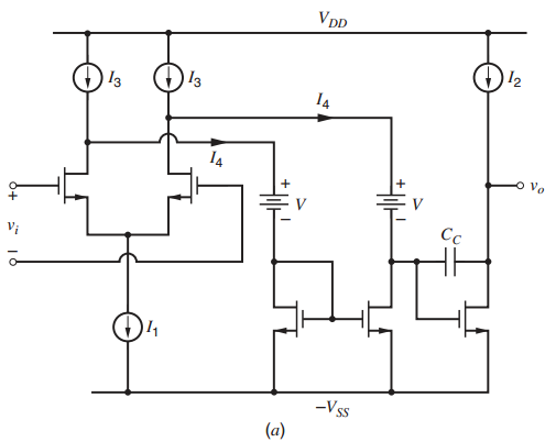
has been inserted between the first and second stages. Assume that current source I1is implemented using an n-channel transistor with overdrive of Vovn, which is equal to the overdrives of the other n-channel transistors shown in Fig. 6.60a. Assume that current sources I2 and I3 are each implemented using one p-channel transistor with an overdrive of Vovp. In the resulting op amp, only n-channel transistors conduct time varying currents. Find the input common-mode range and the maximum output swing of the op-amp in terms of VDD, ˆ’VSS, the level-shift voltage V, the threshold voltages of individual transistors, and the overdrives Vovn and Vovp.
(b) Figure 6.60b shows a realization of an active floating level shift (active battery). Design this level-shift circuit to give a battery voltage of 1.5 V with a small-signal resistance less than 1 k„¦ at I = 100 μA dc. Ignore the body effect. Use IB=100 μA and VDD = VSS =1.65 V. Use SPICE to plot the large-signal Iˆ’V characteristic for V = 0 to 1.65 V. Use μnCox =194 μA/V2, λ = 0, and Vt = 0.6V. For SPICE simulations, connect the lower end of the battery to the negative supply.
Figure 6.60b
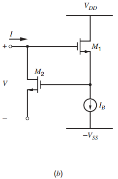
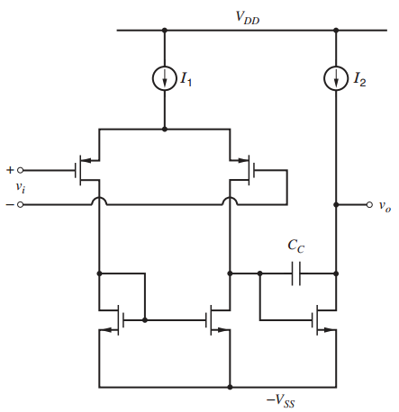
Figure 6.15
Step by Step Answer:
a CM input range To keep the transistor that forms I 1 in the active region V IC V SS V ovn V ov1 V t1 V IC V SS V tI 2V ovn To keep M 1 in the active region V GD1 V t1 V G1 V IC V D1 V SS V t3 V ov3 V V SS V t3 V ovn V V G1 V D1 V t1 V IC V D1 V t1 V SS V t3 V ovn V V t1 So the CM input range is V SS V t1 2V ovn V IC V SS V t3 V ovn V V t1 Output swing V SS V ovn V o ...View the full answer


Analysis and Design of Analog Integrated Circuits
ISBN: 978-0470245996
5th edition
Authors: Paul R. Gray, Paul J. Hurst Stephen H. Lewis, Robert G. Meyer
