

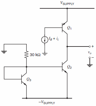
An amplifier stage is shown in Fig. 7.41 where bias current I B is adjusted so that
Question:
(a) Calculate the low-frequency, small-signal trans-resistance Ï…o/ii and use the zero-value time-constant method to estimate the ˆ’3-dB frequency. Data: npn: β = 100, fT = 500 MHz at IC = 1 mA, Cμ0 = 0.7 pF, Cje = 3 pF (at the bias point), Ccs0 = 2 pF, rb = 0, and VA = 120 V. Assume n = 0.5 and ψ0 = 0.55 V for all junctions. pnp: β = 50, fT = 4 MHz at IC = ˆ’0.5 mA, Cμ0 = 1.0 pF, Cje = 3 pF (at the bias point), Cbs0 = 2 pF, rb = 0, and |VA| = 50 V. Assume n = 0.5 and ψ0 = 0.55 V for all junctions.
(b) Repeat (a) if a 20-pF capacitor is connected from collector to base of Q1.
Fig. 7.41:
Fantastic news! We've Found the answer you've been seeking!
Step by Step Answer:
a Q 1 V CB 10 06 94 V V BS 20 06 194 V C 1 764 PF at I C ...View the full answer

Answered By
Divya Munir
I hold M.Sc and M.Phil degrees in mathematics from CCS University, India and also have a MS degree in information management from Asian institute of technology, Bangkok, Thailand. I have worked at a international school in Bangkok as a IT teacher. Presently, I am working from home as a online Math/Statistics tutor. I have more than 10 years of online tutoring experience. My students have always excelled in their studies.
0 Reviews
10+ Question Solved
Related Book For 

Analysis and Design of Analog Integrated Circuits
ISBN: 978-0470245996
5th edition
Authors: Paul R. Gray, Paul J. Hurst Stephen H. Lewis, Robert G. Meyer
Question Posted:
