

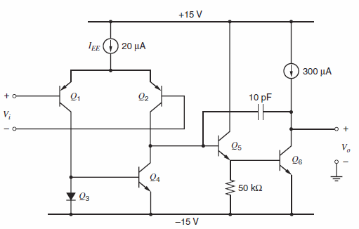
The slew rate of the circuit of Fig. 9.59 is to be increased by using 10 kΩ
Question:
Fig. 9.59:
Fantastic news! We've Found the answer you've been seeking!
Step by Step Answer:
For same unity gain fre...View the full answer

Answered By
User l_884727
0 Reviews
10+ Question Solved
Related Book For 

Analysis and Design of Analog Integrated Circuits
ISBN: 978-0470245996
5th edition
Authors: Paul R. Gray, Paul J. Hurst Stephen H. Lewis, Robert G. Meyer
Question Posted:
