Figure P5.34 shows the diagram of an inverting operational amplifier. a. Assuming an ideal operational amplifier, use
Question:
Figure P5.34 shows the diagram of an inverting operational amplifier.
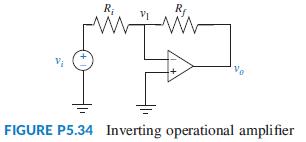
a. Assuming an ideal operational amplifier, use a similar procedure to the one outlined in Problem 52 to find the system equations.
b. Draw a corresponding block diagram and obtain the transfer function Vo(s)/Vi(s).
c. Show that when A → ∞; Vo(s)/Vi(s) = -Rf/Ri.
Data From Problem 52:
Figure P5.33 shows a noninverting operational amplifier.
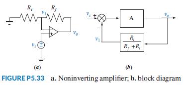
Assuming the operational amplifier is ideal,
a. Verify that the system can be described by the following two equations:
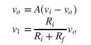
b. Check that these equations can be described by the block diagram of Figure P5.33(b).
c. Use Mason’s rule to obtain the closed-loop system transfer function Vo(s)/Vi(s).
d. Show that when A → ∞; Vo(s)/Vi(s) = 1 + Rf/Ri.
Step by Step Answer:

This question has not been answered yet.
You can Ask your question!