

In the figure is shown a detail of the stationary nozzle diaphragm A and the rotating blades
Question:
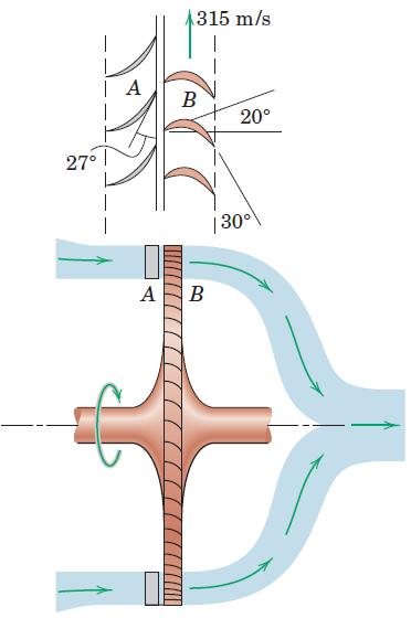
In the figure is shown a detail of the stationary nozzle diaphragm A and the rotating blades B of a gas turbine. The products of combustion pass through the fixed diaphragm blades at the 27° angle and impinge on the moving rotor blades. The angles shown are selected so that the velocity of the gas relative to the moving blade at entrance is at the 20° angle for minimum turbulence, corresponding to a mean blade velocity of 315 m/s at a radius of 375 mm. If gas flows past the blades at the rate of 15 kg/s, determine the theoretical power output P of the turbine. Neglect fluid and mechanical friction with the resulting heat-energy loss and assume that all the gases are deflected along the surfaces of the blades with a velocity of constant magnitude relative to the blade.
Step by Step Answer:


Engineering Mechanics Dynamics
ISBN: 9781118885840
8th Edition
Authors: James L. Meriam, L. G. Kraige, J. N. Bolton
