The RLC circuit shown in Figure P28 can be used as a narrowband filter . If the
Question:
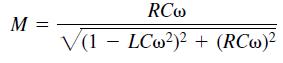
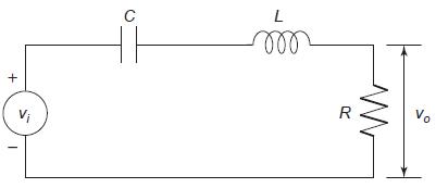
The RLC circuit shown in Figure P28 can be used as a narrowband filter . If the input voltage !i(t) consists of a sum of sinusoidally varying voltages with different frequencies, the narrowband filter will allow to pass only those voltages whose frequencies lie within a narrow range. The magnification ratio M of a circuit is the ratio of the amplitude of the output voltage υo(t) to the amplitude of the input voltage υi(t). It is a function of the radian frequency 2 of the input voltage. Formulas for M are derived in elementary electrical circuits courses. For this particular circuit, M is given by
The frequency at which M is a maximum is the frequency of the desired carrier signal. Determine this frequency as a function of R, C, and L.
Figure P28
Step by Step Answer:
Here taylor series expansion of the function expx2 up to 12th and 14th terms to get 1st six and seve...View the full answer