

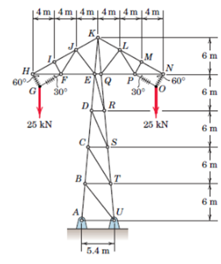
A design model for a transmission-line tower is shown in the figure. Members 0-1, FG, OP, and
Fantastic news! We've Found the answer you've been seeking!
Question:
A design model for a transmission-line tower is shown in the figure. Members 0-1, FG, OP, and NO are insulated cables: all other members are steel bars. For the loading shown, compute the forces in members Fi, FJ, Ej, EK, and ER. Use a combination of methods if desired.
Expert Answer:
Consider the forces acting in horizontal direction at joint I Here F m is the force in the member HI ... View the full answer

Related Book For 
Posted Date:
