

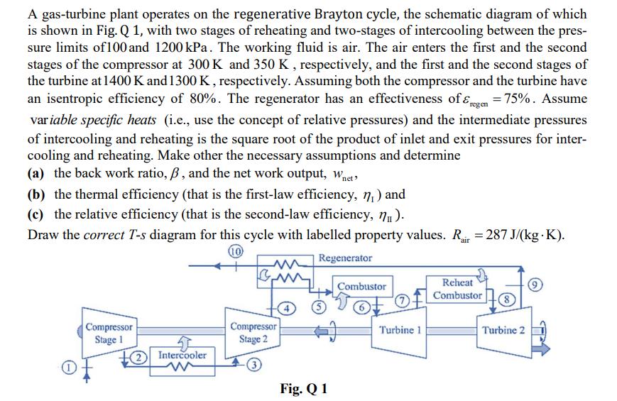
A gas-turbine plant operates on the regenerative Brayton cycle, the schematic diagram of which is shown...
Fantastic news! We've Found the answer you've been seeking!
Question:
Expert Answer:

Related Book For 

Thermodynamics An Engineering Approach
ISBN: 978-0073398174
8th edition
Authors: Yunus A. Cengel, Michael A. Boles
Posted Date:
