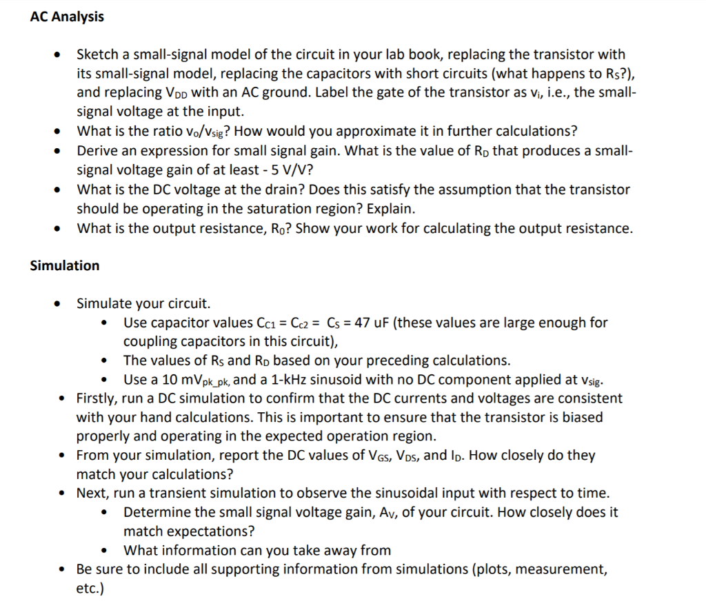
AC Analysis Sketch a small-signal model of the circuit in your lab...
Fantastic news! We've Found the answer you've been seeking!
Question:
Transcribed Image Text:
AC Analysis ● ● ● ● Sketch a small-signal model of the circuit in your lab book, replacing the transistor with its small-signal model, replacing the capacitors with short circuits (what happens to Rs?), and replacing VDD with an AC ground. Label the gate of the transistor as v₁, i.e., the small- signal voltage at the input. What is the ratio vo/Vsig? How would you approximate it in further calculations? Derive an expression for small signal gain. What is the value of Rp that produces a small- signal voltage gain of at least - 5 V/V? What is the DC voltage at the drain? Does this satisfy the assumption that the transistor should be operating in the saturation region? Explain. What is the output resistance, Ro? Show your work for calculating the output resistance. Simulation ● Simulate your circuit. Use capacitor values Cc1 = Cc2 = Cs = 47 uF (these values are large enough for coupling capacitors in this circuit), The values of Rs and RD based on your preceding calculations. Use a 10 mVpk_pk, and a 1-kHz sinusoid with no DC component applied at Vsig. • Firstly, run a DC simulation to confirm that the DC currents and voltages are consistent with your hand calculations. This is important to ensure that the transistor is biased properly and operating in the expected operation region. • From your simulation, report the DC values of VGS, VDs, and l. How closely do they match your calculations? • Next, run a transient simulation to observe the sinusoidal input with respect to time. Determine the small signal voltage gain, Av, of your circuit. How closely does it match expectations? What information can you take away from Be sure to include all supporting information from simulations (plots, measurement, etc.) ● ● ● Table 1: Given Design Parameters Parameter Value 15V 50Ω VDD Rsig R₁ RG1 ID 1mA | Av|=|Vo/Vsig | >= |-5V/V| = RG2 10kQ 10ΚΩ Table 2: Transistor Hand Analysis Values Parameter Vtn UnCox (W/L) VA Value 0.71V 4.5mA/V² 80V ● ● Usig ● Rsig www ● O CC1 Rin RGI VDD Vi RG2 +1₁ (a) 1₁ RD Cc₂ Rs +1₁ 1₁ Ro FIGURE 1 Common-source amplifier circuit, with coupling capacitors, and resistor RG for DC-biasing purposes. Based on Fig. 7.55 p.468 S&S. RL DC Operating Point Analysis Sketch a DC model of the circuit in your lab book, replacing the three "large-valued" coupling capacitors Cc1, Cc2, and C, by open circuits What is the DC current through RG? Based on the information just given, you have enough information to calculate Vov = VGS- Vtn. What is its value? + Vo Determine all resistance values that can be found at this stage. What is the value of gm? What is VGs? Remember: Your actual transistor will have a value of Vtn that will vary from its nominal value, which will alter your measurement results slightly! Calculate to. NOTE: At this point there is not yet enough information to determine RD. We will need to perform small signal analysis. AC Analysis ● ● ● ● Sketch a small-signal model of the circuit in your lab book, replacing the transistor with its small-signal model, replacing the capacitors with short circuits (what happens to Rs?), and replacing VDD with an AC ground. Label the gate of the transistor as v₁, i.e., the small- signal voltage at the input. What is the ratio vo/Vsig? How would you approximate it in further calculations? Derive an expression for small signal gain. What is the value of Rp that produces a small- signal voltage gain of at least - 5 V/V? What is the DC voltage at the drain? Does this satisfy the assumption that the transistor should be operating in the saturation region? Explain. What is the output resistance, Ro? Show your work for calculating the output resistance. Simulation ● Simulate your circuit. Use capacitor values Cc1 = Cc2 = Cs = 47 uF (these values are large enough for coupling capacitors in this circuit), The values of Rs and RD based on your preceding calculations. Use a 10 mVpk_pk, and a 1-kHz sinusoid with no DC component applied at Vsig. • Firstly, run a DC simulation to confirm that the DC currents and voltages are consistent with your hand calculations. This is important to ensure that the transistor is biased properly and operating in the expected operation region. • From your simulation, report the DC values of VGS, VDs, and l. How closely do they match your calculations? • Next, run a transient simulation to observe the sinusoidal input with respect to time. Determine the small signal voltage gain, Av, of your circuit. How closely does it match expectations? What information can you take away from Be sure to include all supporting information from simulations (plots, measurement, etc.) ● ● ● Table 1: Given Design Parameters Parameter Value 15V 50Ω VDD Rsig R₁ RG1 ID 1mA | Av|=|Vo/Vsig | >= |-5V/V| = RG2 10kQ 10ΚΩ Table 2: Transistor Hand Analysis Values Parameter Vtn UnCox (W/L) VA Value 0.71V 4.5mA/V² 80V ● ● Usig ● Rsig www ● O CC1 Rin RGI VDD Vi RG2 +1₁ (a) 1₁ RD Cc₂ Rs +1₁ 1₁ Ro FIGURE 1 Common-source amplifier circuit, with coupling capacitors, and resistor RG for DC-biasing purposes. Based on Fig. 7.55 p.468 S&S. RL DC Operating Point Analysis Sketch a DC model of the circuit in your lab book, replacing the three "large-valued" coupling capacitors Cc1, Cc2, and C, by open circuits What is the DC current through RG? Based on the information just given, you have enough information to calculate Vov = VGS- Vtn. What is its value? + Vo Determine all resistance values that can be found at this stage. What is the value of gm? What is VGs? Remember: Your actual transistor will have a value of Vtn that will vary from its nominal value, which will alter your measurement results slightly! Calculate to. NOTE: At this point there is not yet enough information to determine RD. We will need to perform small signal analysis.
Expert Answer:
Answer rating: 100% (QA)
Here are the stepbystep workings 1 Smallsignal model of the circuit Replace transistor w... View the full answer
Related Book For
Fundamentals of Electric Circuits
ISBN: 9780073301150
3rd edition
Authors: Matthew Sadiku, Charles Alexander
Posted Date:
Students also viewed these accounting questions
-
What is the y parameter presentation of the circuit in Fig. 19.112? 2 2 10
-
The right edge of the circuit in FIGURE EX29.35 extends into a 50 mT uniform magnetic field. What are the magnitude and direction of the net force on the circuit? ww 10 cm 15 V 1- X B= 50 mT FIGURE...
-
the Vo = 10 volt of the circuit in the figure below a .true b. false The cutoff frequency for high pass filter is 2.895 Mhz when R1=1.1 K ohm and C1 = 0.05 pF and Rg = 12K ohm and Rf = 18 Kohm a ....
-
Consider an extendable hash structure where buckets can hold 3 search key values. The entries with the key values listed below are inserted in the following order: 57, 28, 26, 98, 38, 79, 7, 109, 30...
-
What is benchmarking? How does it benefit a company?
-
Here is the lined stack of strings code. Please include well detailed comments with your code. https://introcs.cs.princeton.edu/java/43stack/LinkedStackOfStrings.java.html Modify the...
-
Consider the Hald cement data in Table B.21. a. From the matrix of correlations between the regressors, would you suspect that multicollinearity is present? b. Calculate the variance inflation...
-
In 2010, Amir ante Corporation had pretax financial income of $168,000 and taxable income of $120,000. The difference is due to the use of different depreciation methods for tax and accounting...
-
Prepare the four required closing entries for a company that has the following account balances. Capital Stock 500,000 Rent Revenue 5/s 200,000 Fees Earned 100,000 325,000 300,000 Wage Expense...
-
Comparative Statements of Retained Earnings for Renn-Dever Corporation were reported as follows for the fiscal years ending December 31, 2019, 2020, and 2021. Balance at beginning of year Net Incone...
-
In this chapter, we learned that common stock is often placed into various categoriesblue-chip, growth, income, and so forthand referred to by its size, such as large-, mid-, or small-cap. In this...
-
discuss the issues relative to Lateral Earth Pressure and the importance of Retaining Walls. Discussions may include conceptual and technical issues, design methods, etc. Examples are required.
-
Horizontal standards apply: When a condition is not covered by a specific industry standard When a hazard is not considered to be serious Only in specific situations or industries If a vertical or...
-
Please give a brief description on NIRONE sensor technology 2) Please give a detailed description of how educational institutions can use this technology in operations( as in operations and...
-
What is an ethical dilemma from the film "SuperSize Me"? 2. Who are the stakeholders in the McDonald's-Fast Food Patrons scenario? 3. What is the responsibility of the following groups for the health...
-
16. It takes about 1 hour to drive from Baton Rouge to New Orleans a distance of 1.13 105 m. In that same time period, how many times could light make the round trip, i.e. to New Orleans and back...
-
The problem with super efficiency is: a. Supply chains become less resilient b. Benefits accrue to a smaller number of players c. Wages decrease in an uncompetitive marketplace d. Innovation can...
-
Anna, a high school counselor, devised a program that integrates classroom learning with vocational training to help adolescents at risk for school dropouts stay in school and transition to work...
-
Use nodal analysis to find vo in the circuit of Fig. 10.58. 20 10 mH 10 cos 103, V 2012 4i 302
-
Express the following functions in cosine form: (a) 4 sin ( t - 30o) (b) -2 sin 6t (c) -10sin( t + 20o)
-
Construct the Bode magnitude and phase plots for H(s) = 40(s + 1) / (s + 2) (s + 10), s = j
-
A flow of nitrogen is discharged from a duct with \(M_{2}=0.85, T_{2}=500^{\circ} \mathrm{R}\), and \(p_{2}=28\) psia. The temperature at the inlet is \(560^{\circ} \mathrm{R}\). Compute the pressure...
-
Consider the flow of a perfect gas along a Fanno line. Show that the pressure at the * reference state is given by the relation 1/2 m 2RT, P Ayge(y+1)
-
Air enters a duct with a mass flow rate of \(35 \mathrm{lbm} / \mathrm{sec}\) at \(T_{1}=520^{\circ} \mathrm{R}\) and \(p_{1}=20 \mathrm{psia}\). The duct is square and has an area of \(0.64...
Study smarter with the SolutionInn App