

describe and explain the operation of the equipment used for load cycling on an avery Denison 4oo
Fantastic news! We've Found the answer you've been seeking!
Question:
describe and explain the operation of the equipment used for load cycling on an avery Denison 4oo kN universal testing machine 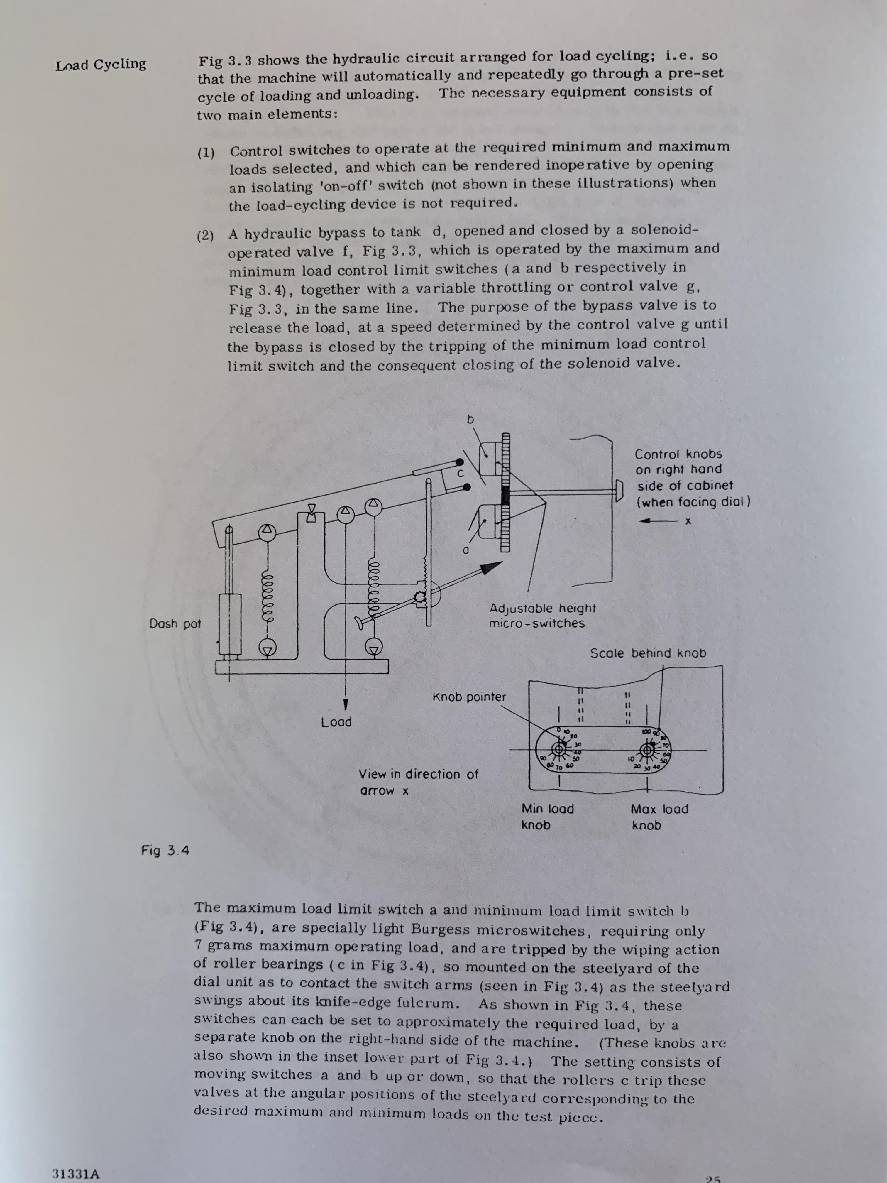
Transcribed Image Text:
Fig 3.3 shows the hydraulic circuit arranged for load cycling; i.e. so that the machine will automatically and repeatedly go through a pre-set cycle of loading and unloading. Load Cycling The necessary equipment consists of two main elements: (1) Control switches to operate at the required minimum and maximum loads selected, and which can be rendered inoperative by opening an isolating 'on-off' switch (not shown in these illustrations) when the load-cycling device is not required. (2) A hydraulic bypass to tank d, opened and closed by a solenoid- ope rated valve f, Fig 3.3, which is operated by the maximum and minimum load control limit switches (a and b respectively in Fig 3. 4), together with a variable throttling or control valve g. Fig 3.3, in the same line. release the load, at a speed determined by the control valveg until the bypass is closed by the tripping of the minimum load control limit switch and the consequent closing of the solenoid valve. The purpose of the bypass valve is to Control knobs on right hand side of cabinet (when facing dial) Adjustable height micro -switches Dash pot Scale behind knob Knob pointer Load 10 60 70 20 30 View in direction of arrow x Min load Max load knob knob Fig 3.4 The maximum load limit switch a and minimum load limit switch b (Fig 3.4), are specially light Burgess microswitches, requiring only 7 gra ms maximum ope rating load, and a re tripped by the wiping action of roller bearings (c in Fig 3.4), so mounted on the steelyard of the dial unit as to contact the switch arms (seen in Fig 3.4) as the steelya rd swings about its knife-edge fulcrum. As shown in Fig 3.4, these switches can each be set to approximately the required load, by a separate knob on the right-hand side of the machine. also shown in the inset lower part of Fig 3.4.) moving switches a and b up or down, so that the rollers c trip these valves at the angular positions of the stcelyard corresponding to the desired maximum and minimum loads on the test piece. (These knobs are The setting consists of 31331A 25 ===D%3= ll ellll The bypass to tank d, Fig 3.3, is coupled up by flexible pipes, and is opened or closed by the action of the solenoid-ope rated piston valve, f in Fig 3.3, wbich is in turn controlled by the two Burgess microswitches, a and b, Fig 3.4. Since a release of load on a microswitch immediately makes or breaks contact, another microswitch is mounted on the solenoid valve to hold it in circuit until the microswitch at the other end of the load cycle operates. The load-cycling attachment is operated by first switching the load-cycle on-off switch from 'off' to the 'load-cycling' position. The maximum load knob and minimum load knob (see inset, Fig 3.4) are then set to the required approximate positions, as shown by the knob pointers on the The knob scales are marked in percentages of full load, and the actual percentages of load are shown on the bezel round the load-indicating The finer setting can be made when the loading and With the load-cycle control valve, scale. dial of the machine. unloading speeds have been adjusted. g in Fig 3.3 wide open, the machine is started with the specimen in position, the pump delive ry and fine straining controls (e and f, Fig 3.1) being adjusted to give the required loading speed, after which the load- cycle control valve is screwed down slowly, to give the required slower unloading speed. Care must be taken that the adjustment of the load-cycle control valve at a low flow limit is such that when the switch operates the load falls, and does not go on increasing to the maximum ma chine load because the pump If the load does not immediately delivery is greater than the return flow. return when the maximum load limit switch operates, either the pump delivery must be reduced or the fine straining control valve slightly An alternative is to open the load-cycle control valve slightly, opened. depending upon whether it is preferred to decrease the loading speed or increase the unloading speed. After test, the specimen is removed and a new one inserted. machine can then be left to load and unload the new specimen while the previous specimen is exa mined by strain gauges, etc. cycles is recorded by an electric counter, shown diagrammatically at i in Fig 3.3, fitted on the front of the machine. The overload precautions of the standard machine are not interfered with in any way, and operate The The number of The load-cycling mechanism is entirely independent. as usual. it is desired to operate the machine as a normal standard tester without using the load-cycling equipment, the maximum load limit switch is set to just beyond a hundred per cent, the minimum load limit switch is set to just below zero, and the load-cycle isolating switch is switched to 'off'. This setting of the load limit switches renders them inoperative. When Fig 3.3 shows the hydraulic circuit arranged for load cycling; i.e. so that the machine will automatically and repeatedly go through a pre-set cycle of loading and unloading. Load Cycling The necessary equipment consists of two main elements: (1) Control switches to operate at the required minimum and maximum loads selected, and which can be rendered inoperative by opening an isolating 'on-off' switch (not shown in these illustrations) when the load-cycling device is not required. (2) A hydraulic bypass to tank d, opened and closed by a solenoid- ope rated valve f, Fig 3.3, which is operated by the maximum and minimum load control limit switches (a and b respectively in Fig 3. 4), together with a variable throttling or control valve g. Fig 3.3, in the same line. release the load, at a speed determined by the control valveg until the bypass is closed by the tripping of the minimum load control limit switch and the consequent closing of the solenoid valve. The purpose of the bypass valve is to Control knobs on right hand side of cabinet (when facing dial) Adjustable height micro -switches Dash pot Scale behind knob Knob pointer Load 10 60 70 20 30 View in direction of arrow x Min load Max load knob knob Fig 3.4 The maximum load limit switch a and minimum load limit switch b (Fig 3.4), are specially light Burgess microswitches, requiring only 7 gra ms maximum ope rating load, and a re tripped by the wiping action of roller bearings (c in Fig 3.4), so mounted on the steelyard of the dial unit as to contact the switch arms (seen in Fig 3.4) as the steelya rd swings about its knife-edge fulcrum. As shown in Fig 3.4, these switches can each be set to approximately the required load, by a separate knob on the right-hand side of the machine. also shown in the inset lower part of Fig 3.4.) moving switches a and b up or down, so that the rollers c trip these valves at the angular positions of the stcelyard corresponding to the desired maximum and minimum loads on the test piece. (These knobs are The setting consists of 31331A 25 ===D%3= ll ellll The bypass to tank d, Fig 3.3, is coupled up by flexible pipes, and is opened or closed by the action of the solenoid-ope rated piston valve, f in Fig 3.3, wbich is in turn controlled by the two Burgess microswitches, a and b, Fig 3.4. Since a release of load on a microswitch immediately makes or breaks contact, another microswitch is mounted on the solenoid valve to hold it in circuit until the microswitch at the other end of the load cycle operates. The load-cycling attachment is operated by first switching the load-cycle on-off switch from 'off' to the 'load-cycling' position. The maximum load knob and minimum load knob (see inset, Fig 3.4) are then set to the required approximate positions, as shown by the knob pointers on the The knob scales are marked in percentages of full load, and the actual percentages of load are shown on the bezel round the load-indicating The finer setting can be made when the loading and With the load-cycle control valve, scale. dial of the machine. unloading speeds have been adjusted. g in Fig 3.3 wide open, the machine is started with the specimen in position, the pump delive ry and fine straining controls (e and f, Fig 3.1) being adjusted to give the required loading speed, after which the load- cycle control valve is screwed down slowly, to give the required slower unloading speed. Care must be taken that the adjustment of the load-cycle control valve at a low flow limit is such that when the switch operates the load falls, and does not go on increasing to the maximum ma chine load because the pump If the load does not immediately delivery is greater than the return flow. return when the maximum load limit switch operates, either the pump delivery must be reduced or the fine straining control valve slightly An alternative is to open the load-cycle control valve slightly, opened. depending upon whether it is preferred to decrease the loading speed or increase the unloading speed. After test, the specimen is removed and a new one inserted. machine can then be left to load and unload the new specimen while the previous specimen is exa mined by strain gauges, etc. cycles is recorded by an electric counter, shown diagrammatically at i in Fig 3.3, fitted on the front of the machine. The overload precautions of the standard machine are not interfered with in any way, and operate The The number of The load-cycling mechanism is entirely independent. as usual. it is desired to operate the machine as a normal standard tester without using the load-cycling equipment, the maximum load limit switch is set to just beyond a hundred per cent, the minimum load limit switch is set to just below zero, and the load-cycle isolating switch is switched to 'off'. This setting of the load limit switches renders them inoperative. When
Expert Answer:
Answer rating: 100% (QA)
Operation of the equipments to be used for load cycling on Avery Dennison 400kN UTM You need to refer fig 33 and 34 for further discription which I am ... View the full answer

Related Book For 

Fundamentals of Taxation 2015
ISBN: 9781259293092
8th edition
Authors: Ana Cruz, Michael Deschamps, Frederick Niswander, Debra Prendergast, Dan Schisler, Jinhee Trone
Posted Date:
Students also viewed these mechanical engineering questions
-
Explain the operation of contribution in insurance using at least 2 examples.
-
Describe and explain the characteristics that distinguish corporations from partner ships and proprietorships.
-
Describe and explain the normal ECG pattern.
-
Which of the following statements are true about REST? Pick ONE OR MORE options Logical URLs should be used instead of physical URLS Adal URLs must always be used in REST response A paging technique...
-
What is the direction of the following equilibrium? H- + H2O H2 + HO-
-
In their book Introduction to Time Series Analysis and Forecasting (Wiley, 2008), Montgomery, Jennings, and Kulahci presented the data on the drowning rate for children between one and four years old...
-
Melissa Khan alleges that on May 27, 2004, she entered into a lease and warranty agreement with Riverbank Motors Corporation, Inc. (the Dealership), for a new, 2004 Volkswagen Toureg (the Vehicle),...
-
Marston Marble Corporation is considering a merger with the Conroy Concrete Company. Conroy is a publicly traded company, and its current beta is 1.30. Conroy has been barely profitable, so it has...
-
The given code snippet is implemented using linear probing technique, what change you have to make so that the quadratic probing is implemented. @Override public boolean put(String word, String...
-
Create a Case Study: Recycle4Change (R4C) - Enabling a Sustainable Recycling System 1. Introduction: Recycle4Change (R4C) is a social enterprise initiative under Chance Creators, affiliated with the...
-
A factory releases a plume into the atmosphere on an overcast summer afternoon. At what distance downwind will the plume begin mixing downward if an inversion layer exists at a base height of 414 m...
-
A proton starts out at the central point of a cyclotron with radius R = 5 0 cm in which a uniform magnetic field B = 1 T is established perpendicular to the plane of motion of the proton. Determine:...
-
Suppose object A is electrically charged and is experiencing forces from three other charged objects. How should the total effects of those three objects be combined in order to find the total...
-
4. How would you find the resistance of a parallel circuit with n identical resistors? (1 mark) I 5. What will be the total resistance and current in a parallel circuit with a 15-volt battery and...
-
Vector A is 5 . 2 units long at a 5 1 0 angle with respect to the positive x - axis. Vector B is 1 5 . 1 units long at an angle of 2 0 5 0 . Determine the difference between the vectors, C = A - B in...
-
The average person passes out at an acceleration of 7 g ( that is , seven times the gravitational acceleration on Earth ) . Suppose a car is designed to accelerate at this rate. How much time would...
-
For running a background application in Linux, what is the corresponding command for opening the notepad ++ application
-
Why should you not model a decision variable as a random variable with a probability distribution?
-
Cameron is single and has taxable income of $59,692. Determine his tax liability using the Tax Tables and using the Tax Rate Schedule. Why is there a difference between the two amounts?
-
Explain how the foreign tax credit limitation works.
-
List the five types of filing status and briefly explain the requirements for the use of each one.
-
Describe the distinctive characteristic of weighted-average computations in assigning costs to units completed and closing work in progress.
-
Refer to requirement 2 of Exercise4.11. Required Prepare summary journal entries for the use of direct materials and conversion costs. Also prepare a journal entry to transfer out the cost of goods...
-
Le Roi du Plastique Sarl has two processes extrusion and thermo-assembly. Consider the June 2022 data for physical units in the thermo-assembly process of Le Roi du Plastique: opening work in...

Study smarter with the SolutionInn App