Following figure shows a diagram for an automobile alarm circuit used to detect certain undesirable conditions. The
Question:
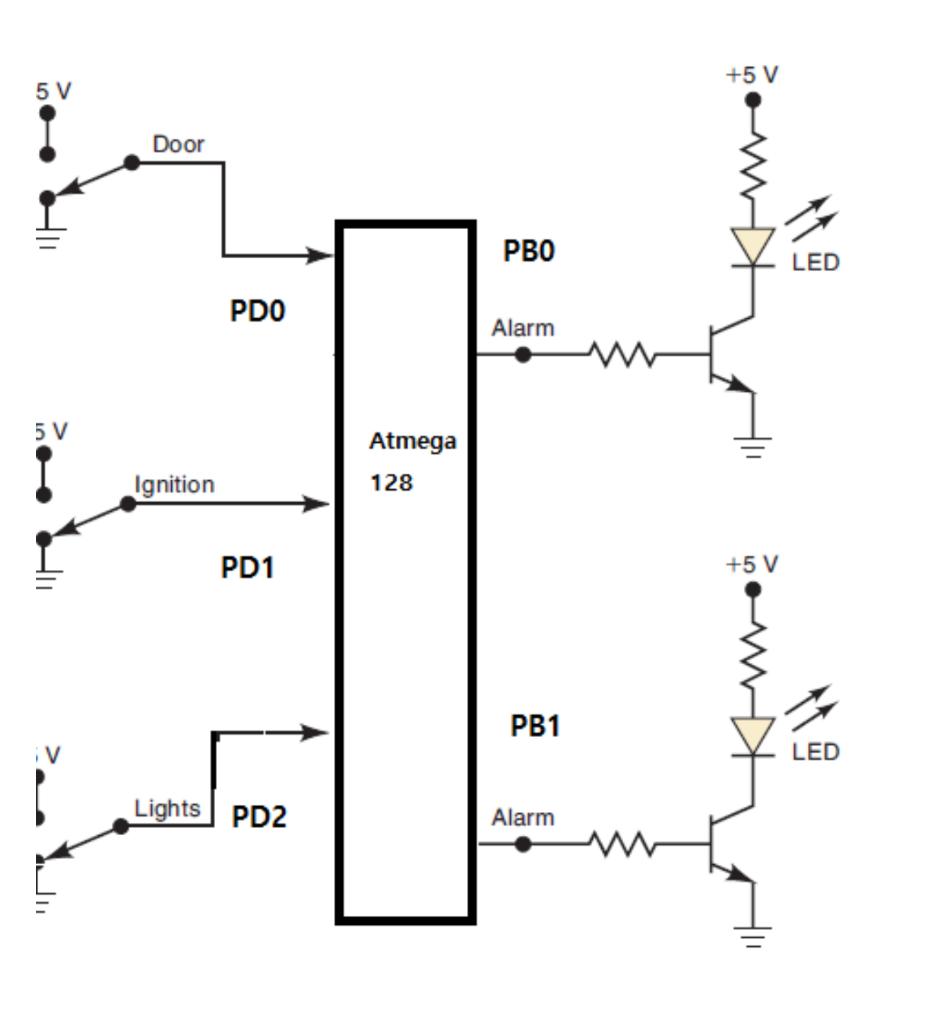
Following figure shows a diagram for an automobile alarm circuit used to detect certain undesirable conditions. The three switches are used to indicate the status of the door by the driver’s seat, the ignition, and the headlights, respectively.
• Atmega 128's I/O D port is used as input and B port is used as output. The three switches are connected to PD0, PD1 and PD2 as shown in the figure. PB0 and PB1 are connected to the alarm, PB0 is an alarm indicating a serious situation, and the alarm connected to PB1 is connected to indicate a general alarm.
1. Write requirements analysis definition document.
• Find out more than 2 references on the web and create a suitable requirements definition form.
Divide the alarm into a major alarm and a general alarm. Indicate the major alarm by the LED connected to PB0 and the general alarm by the LED connected to PB1.
Write all necessary warning conditions for safety. • Ex) The headlights are on while the ignition is off
Explain why
2. Write assembly code with these three switches as inputs so that the alarm will be activated whenever either of your conditions exists:
3. Build in atmel studio and show demo on simulide.
4. Link the demo video
Expert Answer: