

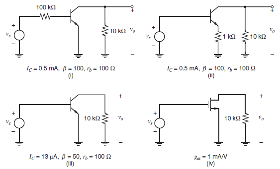
Four methods of achieving an input impedance greater than 100 kΩ are shown in the ac schematics
Question:
(a) Neglecting flicker noise and capacitive effects, derive expressions for the equivalent input noise voltage and current generators of these circuits. For circuit (i) this will be on the source side of the 100-kΩ resistor.
(b) Assuming that following stages limit the bandwidth to dc-20 kHz with a sharp cutoff, calculate the magnitude of the total equivalent input noise voltage in each case. Then compare these circuits for use as low-noise amplifiers from low source impedances.
Fig. 11.50:
Fantastic news! We've Found the answer you've been seeking!
Step by Step Answer:
a i Short inputs and equate noise V 1 V i i i R s Neglecting correlation Ope...View the full answer

Answered By
ANDREW KIPRUTO
Academic Writing Expert
I have over 7 years of research and application experience. I am trained and licensed to provide expertise in IT information, computer sciences related topics and other units like chemistry, Business, law, biology, biochemistry, and genetics. I'm a network and IT admin with +8 years of experience in all kind of environments.
I can help you in the following areas:
Networking
- Ethernet, Wireless Airmax and 802.11, fiber networks on GPON/GEPON and WDM
- Protocols and IP Services: VLANs, LACP, ACLs, VPNs, OSPF, BGP, RADIUS, PPPoE, DNS, Proxies, SNMP
- Vendors: MikroTik, Ubiquiti, Cisco, Juniper, HP, Dell, DrayTek, SMC, Zyxel, Furukawa Electric, and many more
- Monitoring Systems: PRTG, Zabbix, Whatsup Gold, TheDude, RRDtoo
Always available for new projects! Contact me for any inquiries
1+ Reviews
10+ Question Solved
Related Book For 

Analysis and Design of Analog Integrated Circuits
ISBN: 978-0470245996
5th edition
Authors: Paul R. Gray, Paul J. Hurst Stephen H. Lewis, Robert G. Meyer
Question Posted:
